High-pressure gas charging valve and gas fracturing device thereof
A high-pressure gas, filling valve technology, applied in the direction of control valves, valve devices, weapon accessories, etc., can solve the problems of high manufacturing process requirements, high prices, and high processing costs, achieve inflation and ignition, reduce production costs, and simplify effect of structure
- Summary
- Abstract
- Description
- Claims
- Application Information
AI Technical Summary
Problems solved by technology
Method used
Image

Examples
Embodiment 1
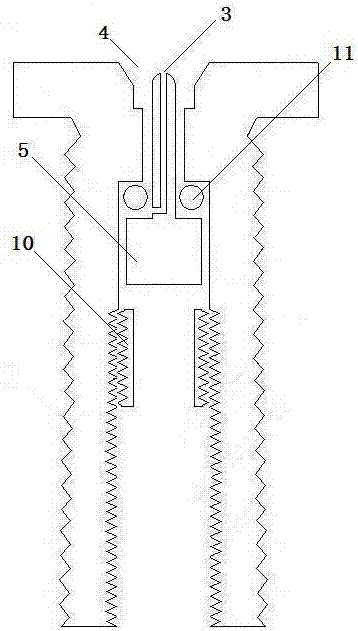
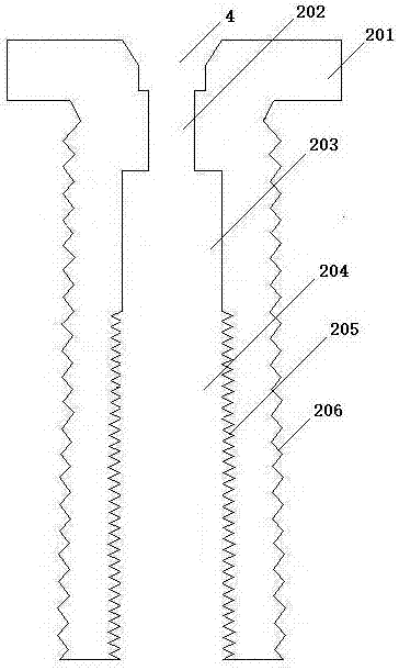
[0031] A high-pressure gas filling valve, comprising an inflatable seat body 201, a through hole 202, a valve chamber 203, an inflatable nozzle 4, an inflatable valve 5, a retaining ring 10 and a first sealing ring 11, and the middle position of the upper end of the inflatable seat body 201 is provided with Inflatable nozzle 4, a through hole 202 is provided below the inflatable nozzle 4, a valve chamber 203 is provided below the through hole 202, a retaining ring 10 is provided below the valve chamber 203, and an inflatable valve 5 and a first sealing ring 11 are arranged in the valve chamber 203; One end of the inflation valve 5 is an inflation thimble 501, and the other end is an inflation valve core 502;
Embodiment 2
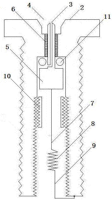
[0033] A gas cracker, comprising an expansion tube 1 and a gas-filled ignition head 2, one end of the expansion tube 1 is sealed, and the other end is provided with a gas-filled ignition head 2, and an energy storage chamber 13 is formed between the sealed end and the gas-filled ignition head 2; The gas-filled ignition head 2 includes a gas-filled seat body 201, a through hole 202, a valve chamber 203, an ignition chamber 204, a gas-filled nozzle 4, a gas-filled valve 5, an insulating layer 6, a heating wire 8, a retaining ring 10 and a first sealing ring 11. An inflatable nozzle 4 is provided in the middle of the upper end of the seat body 201, a through hole 202 is provided below the inflatable nozzle 4, a valve chamber 203 is provided below the through hole 202, an ignition chamber 204 is provided below the valve chamber 203, and an inflatable chamber 203 is provided in the valve chamber 203. The valve 5 and the first sealing ring 11 are provided with a retaining ring 10 in ...
Embodiment 3
[0037] For the gas cracker described in Example 2, in order to facilitate the connection of the heating wire 8, one end of the charging valve 5 is an inflatable thimble 501, the other end is a conductive needle 503, and when the middle part is an inflatable valve core 502, the conductive needle 503 is connected to the heating wire 8 one end, the other end of the heating wire 8 is connected to the inflatable seat body 201; the expansion tube is made of non-ferrous metal material or metal alloy or ABS or steel or copper alloy or aluminum alloy; The energy storage pressure is directly proportional; the material strength of the inflation valve 5 is slightly greater than the energy storage pressure in the energy storage chamber 13 bottle.
[0038] Example 3
[0039] As in the gas cracker described in Embodiment 1 or 2, an internal thread 205 is provided on the inner wall of the ignition chamber 204, and an external thread 206 matching the internal thread 205 is provided on the oute...
PUM
 Abstract
Description
Claims
Application Information
 - R&D
- Intellectual Property
- Life Sciences
- Materials
- Tech Scout
- Unparalleled Data Quality
- Higher Quality Content
- 60% Fewer Hallucinations
Browse by: Latest US Patents, China's latest patents, Technical Efficacy Thesaurus, Application Domain, Technology Topic, Popular Technical Reports.
© 2025 PatSnap. All rights reserved.Legal|Privacy policy|Modern Slavery Act Transparency Statement|Sitemap|About US| Contact US: help@patsnap.com