

Detection device and method for detecting isolation degree and input optical loss indexes of filter plate
A detection device and filter technology, applied in the field of optical communication, can solve problems such as difficulty in batch testing, inability to guarantee the overall quality of filters, low efficiency, etc., achieving easy batch testing, realizing batch testing, and reducing testing time. Effect
- Summary
- Abstract
- Description
- Claims
- Application Information
AI Technical Summary
Problems solved by technology
Method used
Image

Examples
Embodiment Construction
[0032] In order to make the object, technical solution and advantages of the present invention clearer, the specific implementation manners of the present invention will be clearly and completely described below.
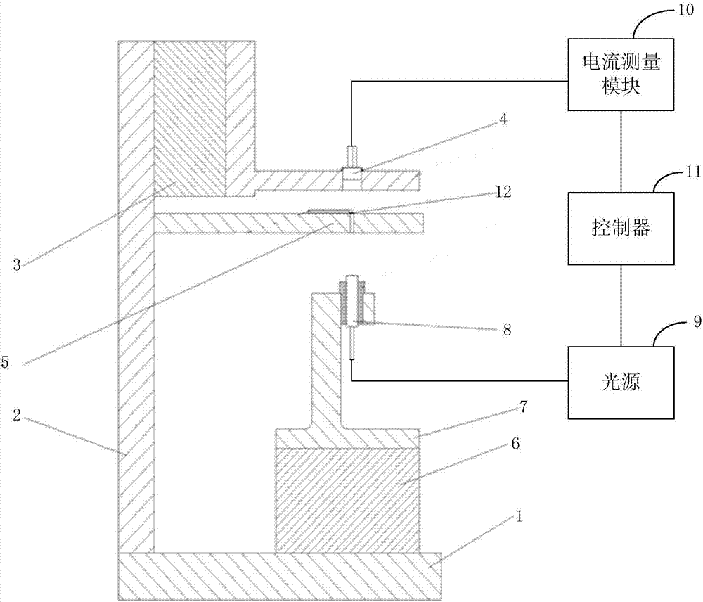
[0033] figure 1 A schematic diagram of the structure and principle of the detection device for the isolation degree of the filter 12 and the input light loss index provided by an embodiment of the present invention. Such as figure 1 As shown, the detection device includes a base 1, a riser 2 installed on the base 1 and perpendicular to the base 1, a Z-axis displacement platform 3 installed on the riser 2, and a photodetector installed on the Z-axis displacement platform 3 4. The filter placement platform 5 installed on the vertical plate 2 and below the Z-axis displacement platform 3, the XY-axis displacement platform 6 installed on the base 1, and the XY-axis displacement platform 6 for fixing the collimator 8 The support column 7, the light source 9 connected wi...
PUM
 Abstract
Description
Claims
Application Information