Water-gas separator

A water-gas separator and water pipe technology, which is applied in the field of tail gas treatment, can solve the problems that small-sized water-gas separators cannot realize liquid level detection, etc., and achieve the effect of reducing economic losses and improving analysis accuracy

Pending Publication Date: 2017-08-18
CHENGDU NANFANG ELECTRONICS METER CO LTD
View PDF16 Cites 1 Cited by
  • Summary
  • Abstract
  • Description
  • Claims
  • Application Information

AI Technical Summary

Problems solved by technology

[0005] In order to solve the problem that the existing small-sized water-gas separator cannot realize liquid level detection, the purpose of the present invention is to provide a water-gas separator with a liquid-level detection function, which can effectively control the liquid level in the water-gas separator in real time. bit

Method used


Image

  • Water-gas separator
  • Water-gas separator
  • Water-gas separator

Examples


Embodiment 1

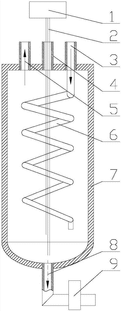
[0052]A water-gas separator, comprising a housing 7, the upper part of the housing 7 is provided with an exhaust gas inlet 3, an exhaust gas outlet 5 and a cable penetration inlet 4, the exhaust gas inlet 3 is mainly used for inletting exhaust gas, the The exhaust gas outlet 5 is mainly for exhausting exhaust gas, and the cable penetration port 4 is used to penetrate the liquid level detection cable 2 into the housing 7; the lower part of the housing 7 is provided with a water outlet 8, and the separated water passes through the water outlet 8 discharge. A drainage pipeline is connected to the water outlet 8 of the water-gas separator, and a drainage valve 9 is arranged on the drainage pipeline. In addition, a liquid level detection cable 2 is also provided, and the liquid level detection cable 2 is mainly used for detecting the liquid level in the water-gas separator. One end of the liquid level detection cable 2 extends into the casing 7 of the water-gas separator, and the ...

Embodiment 2

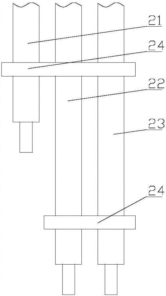
[0054] On the basis of Embodiment 1, the liquid level detection cable 2 is set as three sets of lines, namely, the high water level detection cable 21, the low water level detection cable 22 and the common detection cable 23, and one end of the high water level detection cable 21 1. One end of the low water level detection cable 22 and one end of the common detection cable 23 all extend into the water-air separator, the other end of the high water level detection cable 21, the other end of the low water level detection cable 22 and the common detection cable The other end of 23 is electrically connected with the controller 1 after passing through the water-gas separator. The lower end of the high water level detection cable 21 is higher than the lower end of the low water level detection cable 22, and the lower end of the common detection cable 23 is lower than the lower end of the low water level detection cable 22 or flush with the lower end of the low water level detection c...

Embodiment 3

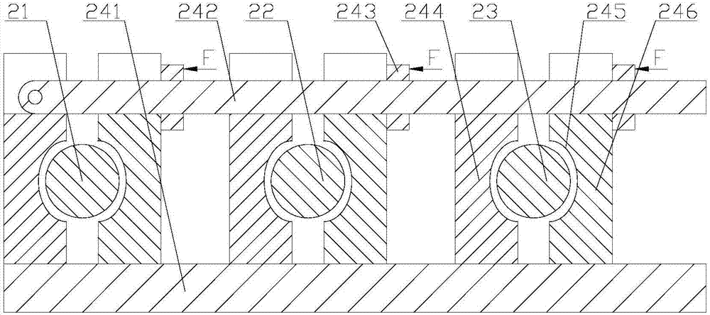
[0056] On the basis of the second embodiment, the liquid level detection cable 2 is also sleeved with a cable clamping assembly, and the high water level detection cable 21, the low water level detection cable 22 and the common detection cable can be connected through the cable clamping assembly. Any two or all of the cables 23 are clamped together.


PUM


Abstract

The invention discloses a water-gas separator and belongs to the technical field of tail gas treatment. The invention aims at providing the water-gas separator with a liquid level detection function and the water-gas separator can be used for effectively controlling a liquid level in the water-gas separator. The water-gas separator comprises a shell body, wherein a tail-gas inlet, a tail-gas outlet and a cable threading-in opening are formed in the upper part of the shell body; a water outlet is formed in the lower part of the shell body; the water outlet is connected with a water drainage pipeline; the water drainage pipeline is provided with a water drainage valve; the water-gas separator is further provided with a liquid level detection cable for detecting the liquid level; one end of the liquid level detection cable stretches into the shell body through the cable threading-in opening; the other end of the liquid level detection cable is electrically connected with a controller; the controller is electrically connected with the water drainage valve. The water-gas separator is applicable to water removal treatment of tail gas.

Description

technical field [0001] The invention belongs to the technical field of tail gas treatment and relates to a water removal device for water removal treatment of tail gas. Background technique [0002] In the chemical production process detection and analysis system, the process gas produced by the factory or the tail gas discharged from the equipment contain more complex components, and the water content in the tail gas is relatively high. If the tail gas enters the analyzer directly without any treatment, the tail gas content analyzed by the later analysis equipment will be inaccurate. At the same time, because the toxic and harmful substances in the tail gas are mostly corrosive media, acidic substances will be generated in the presence of moisture. Corrosion of the back-end pipeline and analysis equipment, seriously affecting the analysis equipment. Therefore, these gases need to be pretreated before entering the analyzer, and the moisture in the tail gas is removed throug...

Claims


Application Information

Patent Timeline
Patent Type & Authority Applications(China)
IPC IPC(8): G01N1/34
CPCG01N1/34
Inventor 范连军黄金义熊凯刘聪陈飞
Owner CHENGDU NANFANG ELECTRONICS METER CO LTD
Why Eureka
Try Eureka