Device and method for multispot scanning microscopy

一种扫描显微、设备的技术,应用在显微镜、仪器、分析材料等方向,能够解决噪声增加、不能配置、图像记录慢等问题,达到光损伤减少、实现扫描速度、灵活光学布置的效果

Active Publication Date: 2017-08-18
CARL ZEISS MICROSCOPY GMBH
View PDF16 Cites 3 Cited by
  • Summary
  • Abstract
  • Description
  • Claims
  • Application Information

AI Technical Summary

Problems solved by technology

[0005] However, this method still has a series of problems
These issues include: first, a significant propensity for fluorescence to bleach and often cause photodamage to the sample; second, relatively slow image recording; and third, increased noise compared to widefield methods
[0007] Despite its very widespread spread in the life sciences, confocal microscopy in particular has the problem that in order to generate information with an acceptable signal-to-noise ratio (SNR), a certain number of photons must be generated in a short time (e.g., For detecting 10 photons in 1 μs pixel time with an SNR of about 3, that is a 10 MHz rate signal photon; due to losses in the system, the rate in the sample must be much higher)
However, color channels are thus fixedly predefined and not configurable
Thus, since the wavelength distribution is fixedly predefined, the system cannot be optimized in the case of samples containing fewer dyes than can in principle be detected with respect to other parameters such as, for example, sample storage or speed.

Method used


Image

  • Device and method for multispot scanning microscopy
  • Device and method for multispot scanning microscopy
  • Device and method for multispot scanning microscopy

Examples


Embodiment Construction

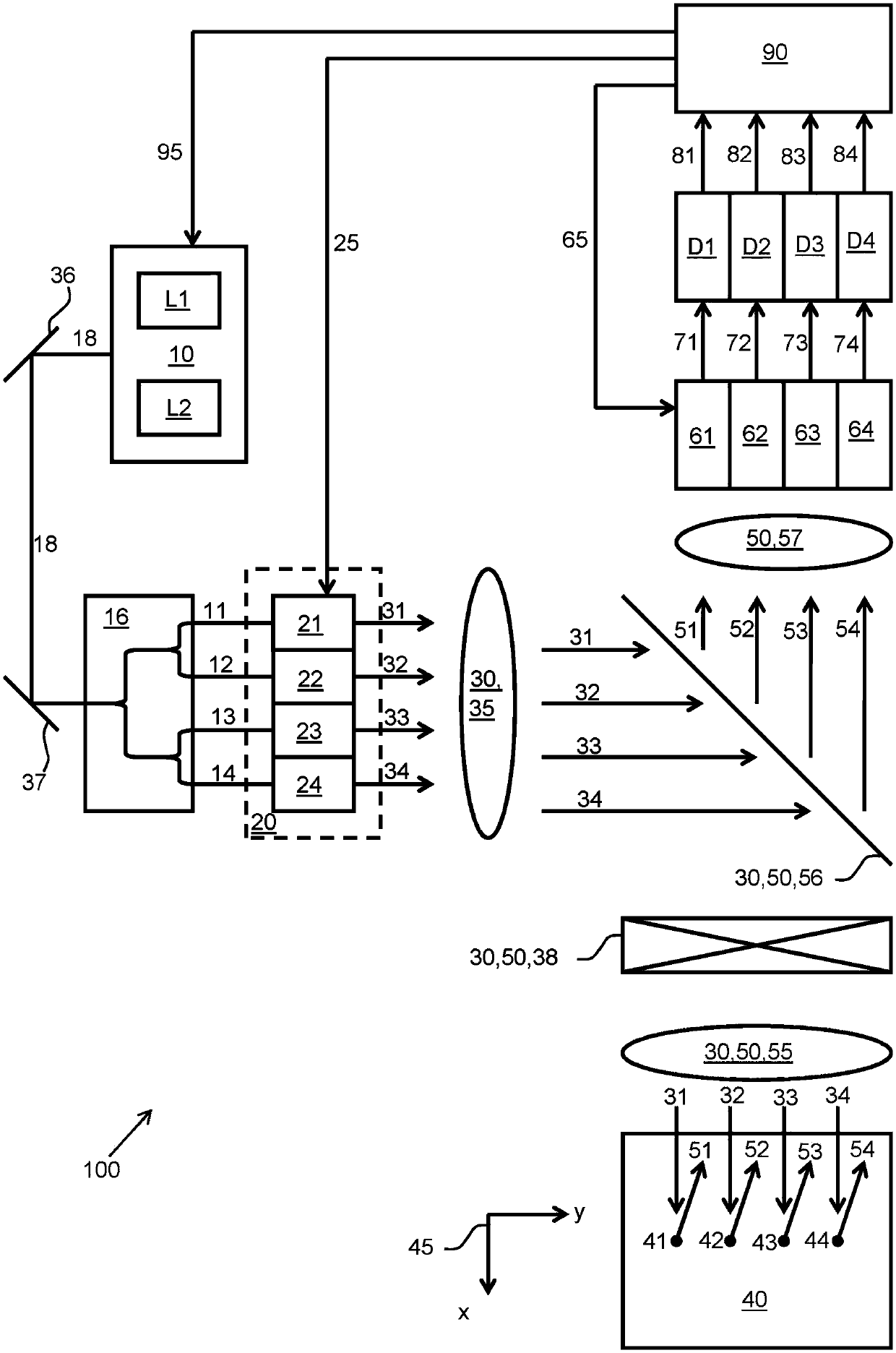
[0063] The basic principle of the measurement with the device according to the invention is based on laser scanning microscopy. The optical arrangement of the microscope is designed such that parallel mode operation is optically produced. Crucially, multiple illumination beams can be coupled into the microscope.

[0064] A specific number of laser lines can be provided to the microscope for spectral illumination. First, it is irrelevant whether they are discrete laser lines, tunable lasers, or white-light lasers. Also, it doesn't matter whether the laser is continuous or pulsed. Finally, the applicability of the invention is not limited to specific excitation mechanisms such as eg conventional fluorescence excitation. Non-linear processing can be used, such as, inter alia, two-photon fluorescence or two-photon processing in CARS microscopy. In particular, primary color beamsplitters can be used to reflect these spectral components into the light path of the microscope. Fo...


PUM


Abstract

The invention relates to a device for multispot scanning microscopy, having a multicolour light source for providing at least one illumination light beam, having a splitting device for splitting the illumination light beam into a plurality of illumination sub-beams, having first optical means for providing an illumination optical path for guiding and focussing the individual illumination sub-beams respectively into a light spot on or in a specimen to be examined, having a scan unit for guiding the light spots over the probe, having a detection unit for detecting detection light emitted by the specimen in detection sub-beams after irradiation with the individual illumination sub-beams, having second optical means for providing a detection optical path for guiding the detection sub-beams to the detector unit, having a control and evaluation unit for controlling the scan unit and for evaluating the detection light detected by the detection unit. The device is characterised in that in the illumination optical path for at least two of the illumination sub-beams a controllable beam manipulation means is present for independent setting of a spectral composition of the respective illumination sub-beam, and the control and evaluation unit is designed to control the beam manipulation means. The invention further relates to a method for multispot scanning microscopy.

Description

technical field [0001] In a first aspect, the invention relates to an apparatus for multipoint scanning microscopy according to the preamble of claim 1 . In a second aspect, the invention relates to a method for multipoint scanning microscopy according to the preamble of claim 24 . Background technique [0002] For example, in WO 13 131 808 A1 a common device for multipoint scanning microscopy is described, which has the following components: a polychromatic light source for providing at least one illumination beam; a beam splitter for Splitting the illumination beam into a plurality of illumination sub-beams; a first optical device, which provides an illumination optical path to guide and focus the individual illumination sub-beams into spots on or in the sample to be inspected; scanning A unit for guiding a light spot above the sample; a detection unit for detecting detection light irradiated by the sample in a detection sub-beam after irradiation with a separate illumina...

Claims


Application Information

Patent Timeline
Patent Type & Authority Applications(China)
IPC IPC(8): G01N21/64G02B21/00
CPCG01N21/6458G02B21/0032G02B21/0064G02B21/0076G02F1/113G02F1/116G02B21/008
Inventor 蒂莫·安胡特丹尼尔·施韦特托比亚斯·考夫霍尔德布克哈德·罗舍尔斯特凡·威廉
Owner CARL ZEISS MICROSCOPY GMBH
Why Eureka
Try Eureka