
A high-resolution azimuth method for shipborne high-frequency ground wave radar based on virtual aperture

A technology of high-frequency ground wave radar and virtual aperture, which is applied in the direction of radio wave measurement systems and instruments, can solve the problems of low azimuth resolution, high-resolution methods cannot be directly applied, and cannot distinguish adjacent targets well, achieving Signal-to-clutter ratio improvement and the effect of suppressing first-order sea clutter

Active Publication Date: 2019-09-13
HARBIN INST OF TECH
View PDF8 Cites 0 Cited by
  • Summary
  • Abstract
  • Description
  • Claims
  • Application Information

AI Technical Summary

Problems solved by technology

[0008] The purpose of the present invention is to solve the existing technology to improve the shipboard high-frequency ground wave radar when detecting sea surface targets, which is limited by the actual array aperture, and the azimuth resolution is low when carrying out azimuth resolution of multiple sea surface targets, which cannot be very good In order to distinguish the shortcomings of adjacent targets and the shortcomings of traditional high-resolution methods that cannot be directly applied to shipboard conditions due to the influence of first-order sea clutter, a high-frequency ground-wave radar-based high-resolution method for sea surface target azimuth is proposed

Method used

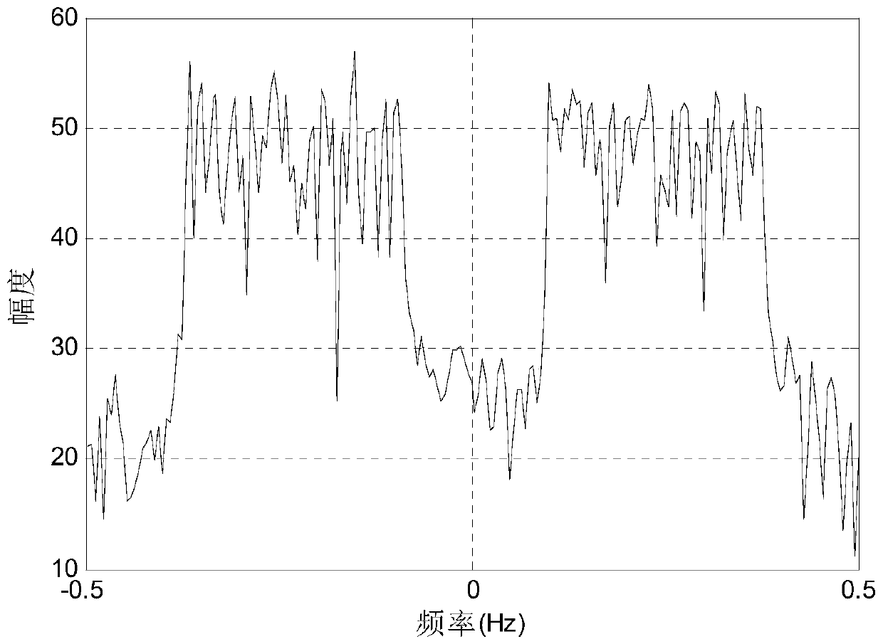
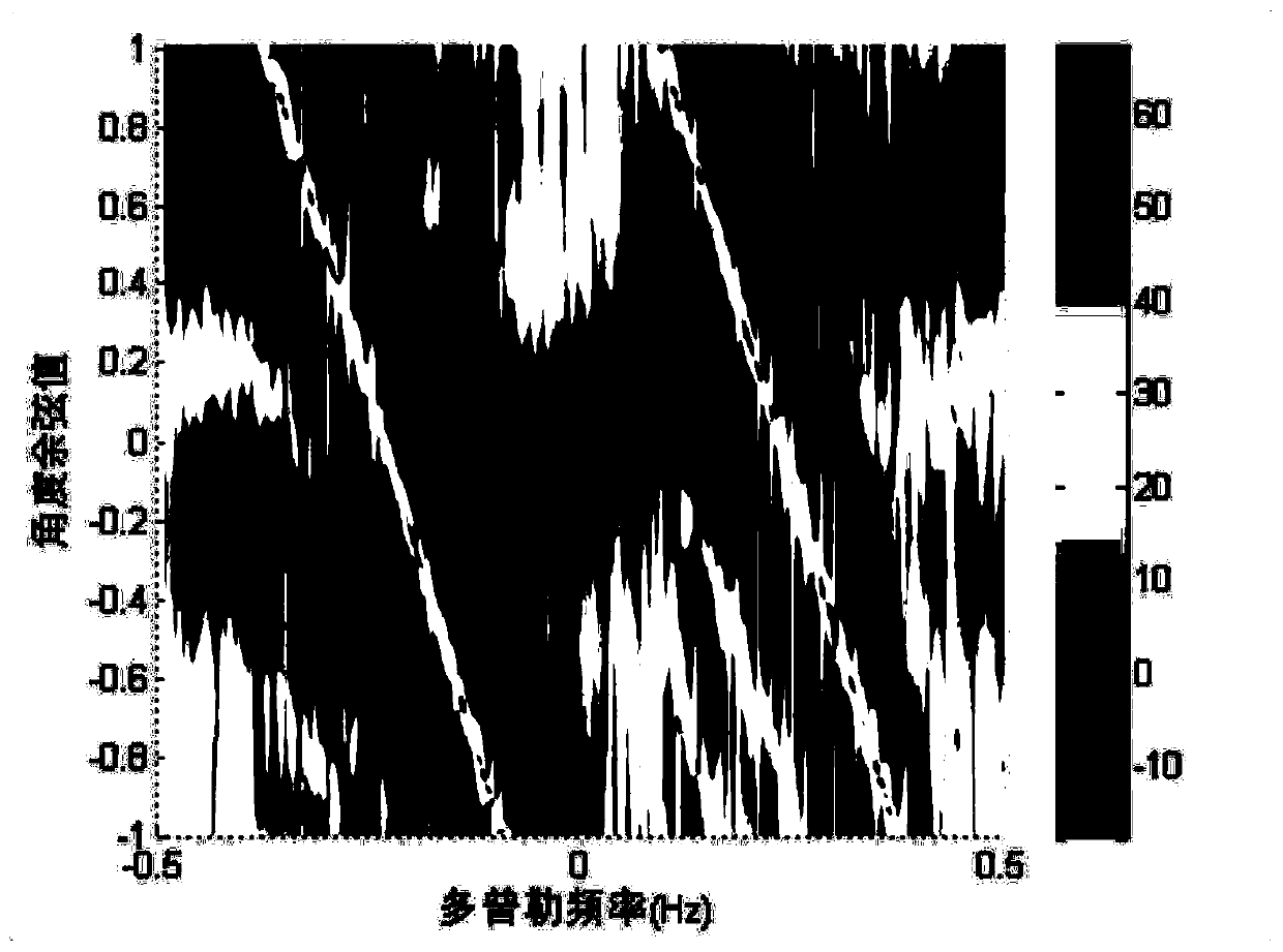
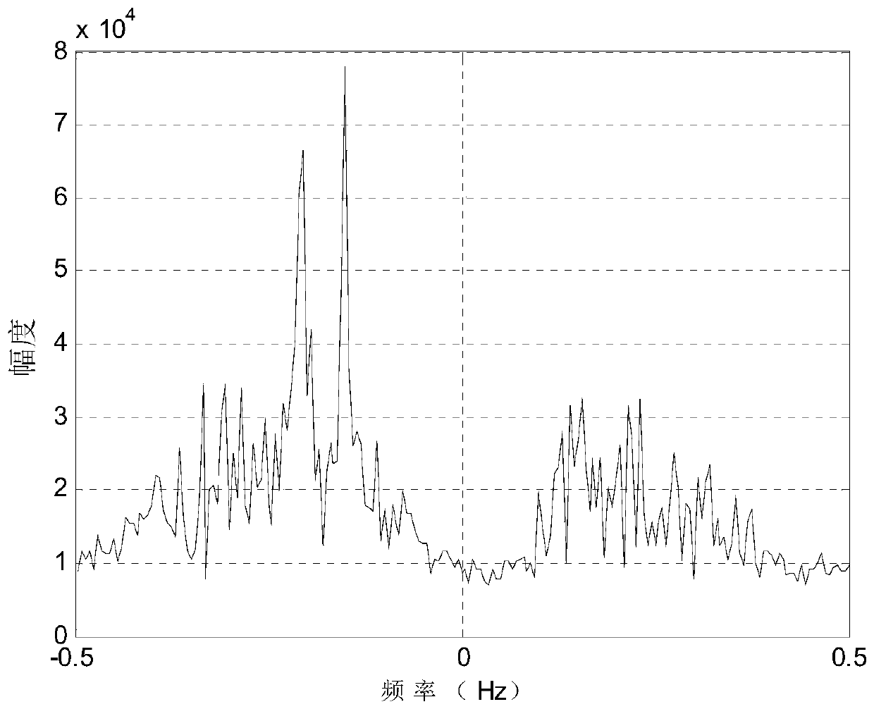

Image

  • A high-resolution azimuth method for shipborne high-frequency ground wave radar based on virtual aperture
  • A high-resolution azimuth method for shipborne high-frequency ground wave radar based on virtual aperture
  • A high-resolution azimuth method for shipborne high-frequency ground wave radar based on virtual aperture

Examples


specific Embodiment approach 1

[0032] Specific embodiment one: a kind of shipborne high-frequency ground wave radar azimuth high-resolution method based on virtual aperture comprises the following steps:

[0033] Step 1: Set the antenna array of the shipboard high-frequency ground wave radar as a linear array, the number of array elements is M, and M is a positive integer greater than 3, the signal received by the antenna array of the radar is X(q), and the matrix X( q in each pulse period in q 1 ,q 2 ,q 3 ,...,q c The signals at the sampling time are respectively FFTed to obtain the Doppler spectrum F of the echoes of M array elements at each sampling time q1 (s), F q2 (s),...,F qc (s); The FFT is a Fast Fourier Transform, and q is a sequence of sampling moments, and q=[q 1 ,q 2 ,...,q c ], where q 1 ,q 2 ...q c is the sampling time, c is the total number of time-domain samples in each pulse period; the distance between the array elements is d, the wavelength of the radar signal is λ, the pulse ...

specific Embodiment approach 2

[0041] Specific embodiment two: the difference between this embodiment and specific embodiment one is: the Doppler matrix F of the echoes of the M array elements at each sampling moment is obtained in the step one q1 (s), F q2 (s),...,F qc (s) The specific process is:

[0042] Assuming that the distance between the elements of the antenna array is d, the wavelength of the radar signal is λ, the pulse width is τ, d needs to satisfy d≤λ / 2, and the speed of the array platform is v, the signal received by the radar antenna array is:

[0043]

[0044] x n,m (q) is the received signal of the mth array element of the radar antenna array in the nth pulse repetition period

[0045] Take the first column in the matrix X(q), that is, take the received signal of the first array element:

[0046]

[0047] Take q in each pulse period 1 ,q 2 ...,q c The signals at the sampling time are respectively subjected to fast Fourier transform (FFT) to obtain the Doppler spectrum at all s...

specific Embodiment approach 3

[0058] Specific implementation mode three: the difference between this implementation mode and specific implementation mode one or two is: the q obtained in step one in said step two 1 The Doppler matrix F of the echoes of M array elements at the sampling time q1 (s), use the orthogonal projection algorithm to suppress the first-order sea clutter in the frequency domain, and obtain the suppressed echo signal Doppler matrix F DPRS (s) The specific process is:

[0059]

[0060] In the formula, F DPRS (s) is the Doppler matrix of the echo signal suppressed by the orthogonal projection algorithm, w(1) P×M , w(2) P×M ,...,w(N) P×M are respectively the orthogonal weighting factors corresponding to the 1st, 2nd, ..., R Doppler units, p is the angle sequence, p=[p 1 ,p 2 ,...,p k ]∈[0,180], k is the total number of elements in the angle sequence, [f p1 (s 1 ), f p2 (s 1 ),...,f pk (s 1 )] T =w(1) p×M ×[f 1,1 (s 1 ), f 2,1 (s 1 ),...,f m,1 (s 1 ),...,f M,1 (s ...


PUM


Abstract

The invention provides a shipborne high frequency surface wave radar (HFSWR) orientation high-resolution method based a virtual aperture, and the invention relates to a shipborne high frequency surface wave radar (HFSWR) target orientation high-resolution method. The method solves the problem that a traditional synthetic aperture method cannot be applied in sea state environment and the problem that a traditional shipborne HFSWR signal processing method cannot distinguish adjacent targets in an orientation direction. An echo signal is processed in a Doppler domain using an orthogonal projection algorithm firstly, and a target and a Doppler frequency at which the target is are detected; an array is divided into three sub arrays then, sea clutter suppression is performed using the orthogonal projection algorithm through utilization of signals of the sub arrays at the Doppler frequency at which the target is, and the sub array signals are equivalent to signal array element signals; and, finally, virtual aperture processing and wave-beam formation are performed on the three equivalent array element receiving signals by using overlapping of the related algorithms, and a high-resolution result of a target orientation is obtained. The method is applied in radar target orientation estimation and distinguishing fields.

Description

technical field [0001] The invention belongs to the field of radar target detection, and in particular relates to a high-resolution method for target azimuth of a shipboard high-frequency ground wave radar. Background technique [0002] Shipborne high frequency surface wave radar (High Frequency Surface Wave Radar, HFSWR) is a new type of radar that uses high-frequency electromagnetic waves to detect sea surface targets or sea-skimming low-altitude targets. It works in the frequency range of 3-30MHz. The vertically polarized antenna emits electromagnetic waves in the high frequency band, and uses the vertically polarized electromagnetic waves to propagate along the surface with small attenuation to achieve large-scale detection; it uses the surface diffraction effect of high frequency band electromagnetic waves. , can break through the limitation of the curvature of the earth and achieve the effect of beyond the horizon. However, limited by the length of the ship itself, th...

Claims


Application Information

Patent Timeline
Patent Type & Authority Patents(China)
IPC IPC(8): G01S7/41
Inventor 李高鹏蒋坤王思文田文龙谢俊好
Owner HARBIN INST OF TECH
Learn More