
S/L-frequency band planar self-tracking antenna

A self-tracking, frequency-band technology, applied to antennas, antenna arrays, devices that enable antennas to work in different bands at the same time, can solve problems that have not been reported on flat-panel self-tracking antennas, and achieve increased GT value, increased gain, and expanded bandwidth Effect

Inactive Publication Date: 2017-08-18
BEIJING RES INST OF TELEMETRY +1
View PDF3 Cites 6 Cited by
  • Summary
  • Abstract
  • Description
  • Claims
  • Application Information

AI Technical Summary

Problems solved by technology

[0005] At present, there are very few domestic researches on flat-panel self-tracking antennas, and there are no reports on flat-panel self-tracking antennas with S and L dual-frequency duplexes.

Method used


Image

  • S/L-frequency band planar self-tracking antenna
  • S/L-frequency band planar self-tracking antenna
  • S/L-frequency band planar self-tracking antenna

Examples


Embodiment Construction

[0027] The present invention will be described in further detail below in conjunction with the accompanying drawings.

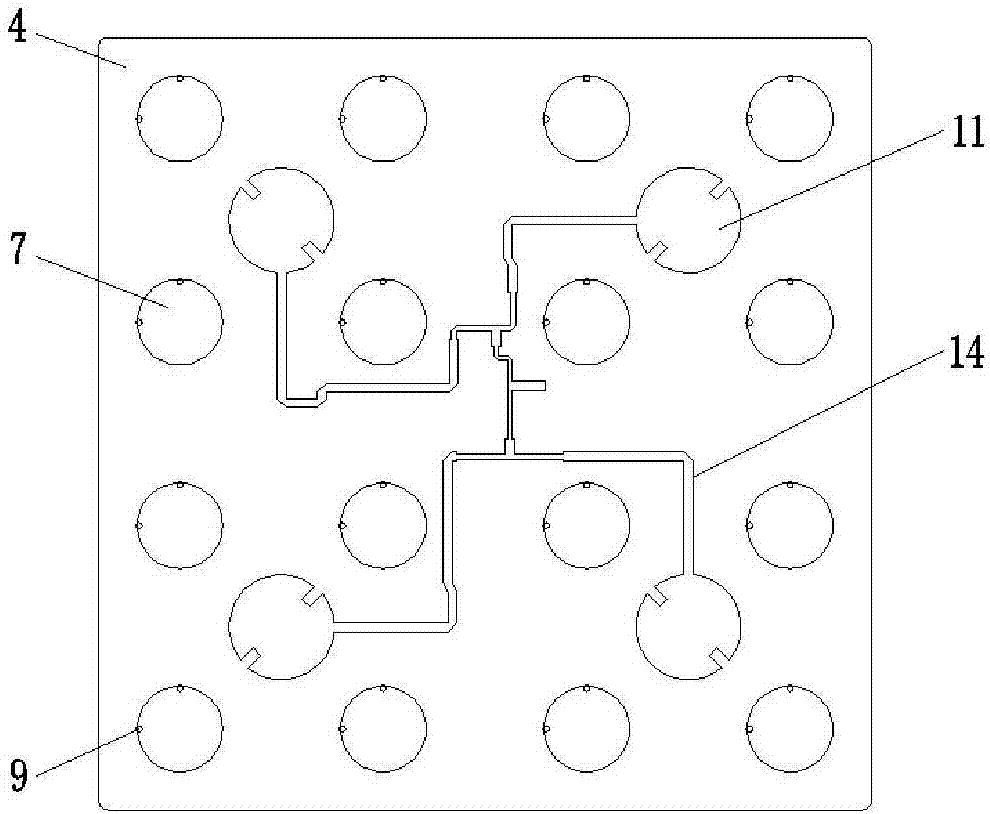
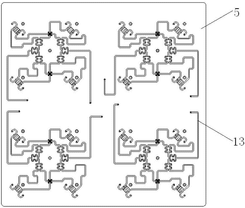
[0028] figure 1 It is a schematic diagram of the side-section structure of the S / L frequency band panel self-tracking antenna of the present invention, figure 2 is a structural schematic diagram of the antenna array printed board of the present invention, image 3 is a schematic structural diagram of the S-band network printed board of the present invention, Figure 4 It is a schematic diagram of the rear-view cover-opening structure of the S / L frequency band flat-panel self-tracking antenna of the present invention. As shown in the figure, the S / L band flat-panel self-tracking antenna includes: radome 1, antenna shell 2, inner cavity support structure 3, antenna array printed board 4, S-band network printed board 5, and S-band antenna unit , L-band antenna unit, S-band network printed line 13, L-band network printed line 14, S-band and differential 15 an...


PUM


Abstract

The present invention discloses an S / L-frequency band planar self-tracking antenna. The S / L-frequency band planar self-tracking antenna comprises a radome, an antenna housing, an inner cavity supporting structure, an antenna array plane printed circuit board, an S-frequency band network printed circuit board, an S-frequency band antenna unit, an L-frequency band antenna unit, an S-frequency band network printed line, an L-frequency band network printed line, an S-frequency band sum-difference modulator and an S-frequency band low-noise filtering assembly; the S-frequency band antenna unit includes an S-frequency band orienting sheet, an S-frequency band radiation patch, an S unit supporting column and a feed pin; the L-frequency band antenna unit comprises an L-frequency band orienting sheet, an L-frequency radiation patch and an L unit supporting column; the S-frequency band network printed line is arranged at the lower surface of the S-frequency band network printed circuit board; the L-frequency band network printed line is arranged at the upper surface of the antenna array plane printed circuit board; and the S-frequency band sum-difference modulator and the S-frequency band low-noise filtering assembly are installed at the lower surface of the inner cavity supporting structure. The S / L-frequency band planar self-tracking antenna of the invention has the advantages of decreased size, reduced weight and improved gain.

Description

technical field [0001] The invention relates to the technical field of antennas, in particular to an S / L frequency band flat panel self-tracking antenna. Background technique [0002] At present, domestic telemetry ground receiving stations generally use parabolic reflector antennas with high gain to track flying targets. However, parabolic antennas have the disadvantages of high development cost, large size, and inconvenient use in mobile or portable telemetry receiving stations. [0003] With the development of technologies in communication, navigation, remote control and telemetry in our country, the application and development of the "communication in motion" communication system is very rapid. The existing parabolic antenna can no longer fully adapt to the new requirements. [0004] The panel antenna has the advantages of small size, low profile, and light weight. Under the same gain requirements, the size is significantly smaller than the parabolic antenna, and it is...

Claims


Application Information

Patent Timeline
IPC IPC(8): H01Q1/38H01Q21/00H01Q5/28
CPCH01Q1/38H01Q5/28H01Q21/00
Inventor 赵波马琳李靖李连辉张春
Owner BEIJING RES INST OF TELEMETRY
Learn More