Supercharge Your Innovation With Domain-Expert AI Agents!

Variable capacity vane pump

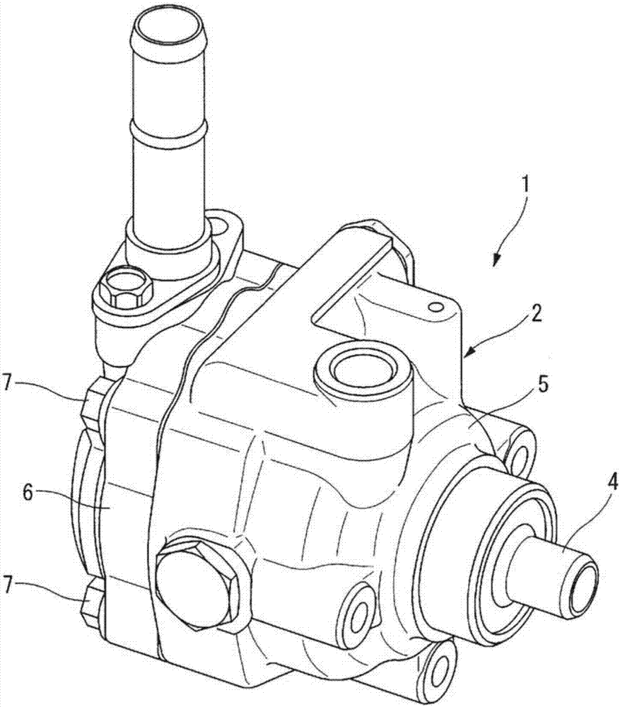
A vane pump and capacity technology, applied in the direction of rotary piston pumps, pumps, pump control, etc., can solve problems such as energy loss, achieve the effect of reducing energy loss and suppressing large-scale

Inactive Publication Date: 2017-08-18
HITACHI AUTOMOTIVE SYST LTD
View PDF7 Cites 1 Cited by
  • Summary
  • Abstract
  • Description
  • Claims
  • Application Information

AI Technical Summary

Problems solved by technology

[0004] However, when such a variable displacement vane pump is used in a power steering device of a vehicle, the hydraulic fluid is also discharged to the power steering device when the vehicle is going straight and hardly requires steering assist by hydraulic pressure. , which may result in energy loss

Method used


Image

  • Variable capacity vane pump
  • Variable capacity vane pump
  • Variable capacity vane pump

Examples


no. 2 approach 〕

[0104] Figure 11 ~ Figure 13 The second embodiment of the present invention is shown, and the basic structure is the same as that of the first embodiment, but a spring having a nonlinear spring constant (non-linear spring) is used as the coil spring 53 .

[0105] That is, the coil spring 53 of the present embodiment is formed such that at least one of design parameters such as coil diameter, pitch, and wire diameter varies along the axial direction of the coil spring 53, and thus the spring load F is different from that of nature. The relationship of displacement x from the length (hereinafter, simply referred to as “displacement x”) becomes nonlinear.

[0106] also, Figure 11 and Figure 12 is a diagram showing the relationship between the spring load F and the displacement x in an example of the coil spring 53 used in this embodiment, Figure 11 Indicates a so-called 2-stage pitch spring with different pitches on one end side and the other end side, Figure 12 Indicate...

no. 3 approach 〕

[0114] Figure 14 The third embodiment of the present invention is shown, and the basic structure is the same as that of the first embodiment, but the structure of the pump casing 2 is changed. In addition, in the following description, the same code|symbol is attached|subjected to the same structural part as 1st Embodiment, and a specific description is abbreviate|omitted.

[0115] That is, if Figure 14 As shown, the pump casing 2 of this embodiment is composed of a front casing 5 which is a flat first casing and a rear casing 6 which is a bottomed cylindrical second casing. Furthermore, the pump member housing chamber 2 a is formed inside by closing the opening of the rear housing 6 with the inner end surface of the front housing 5 on the rear housing 6 side.

[0116] In addition, as the structure of the pump housing 2 is changed, the fitting ring 8 constituting the pump member 3 is fitted and fixed to the inner peripheral surface of the cylindrical portion 6 b of the rea...


PUM


Abstract

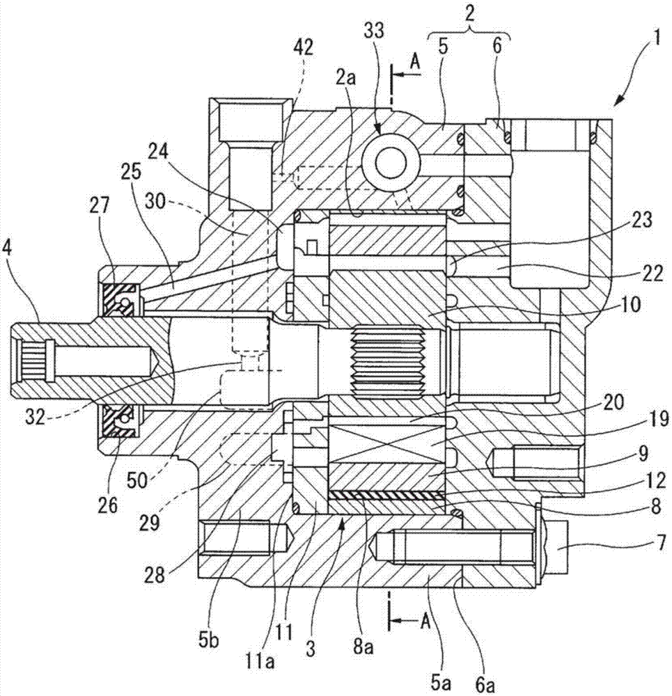
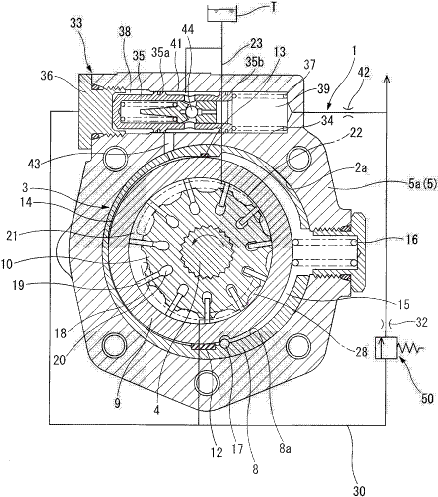
A variable capacity vane pump 1 that supplies operating oil to a power steering device and is equipped with: a pump housing 2, comprising a bottomed cylindrical front housing 5 and a rear housing 6 that closes off the front housing; a pumping element 3 that is housed within the pump housing, and communicates with a suction passage 23 and a discharge passage 30 to draw in and to discharge the operating oil; and a flow volume control valve 33 that controls the amount of operating oil discharged by the pumping element. A pressure-sensitive valve 50, which changes the flow path cross-sectional area of the discharge passage so as to increase the discharge amount of the pumping element in conjunction with an increase in the load pressure of the power steering device, is provided midway along the discharge passage, on the bottom wall portion 5b of the front housing. Thus, when applied to a power steering device, an increase in the size of the device can be avoided while reducing energy loss.

Description

technical field [0001] The present invention relates to variable capacity vane pumps for hydraulic power steering devices such as automobiles. Background technique [0002] Generally, a variable displacement vane pump includes: a pump housing having a pump member housing inside, a pump member that is rotationally driven by an engine to suck and discharge hydraulic fluid, and a discharge passage that guides the hydraulic fluid discharged from the pump member to a supply destination. , an orifice provided in the middle of the discharge passage, and a flow control valve for controlling the discharge amount of the working fluid of the pump member based on the differential pressure across the orifice. [0003] The differential pressure before and after the orifice changes according to the discharge amount of the pump member, which is determined based on the rotational speed of the engine. That is, the variable displacement vane pump controls the flow rate of the working fluid ba...

Claims


Application Information

Patent Timeline
Patent Type & Authority Applications(China)
IPC IPC(8): F04C14/22F04C2/344
CPCF04C2/344F04C2/3441F04C14/226F04C2240/811F04C2270/215F04C14/22F04C14/223F04C14/24
Inventor 今永广喜
Owner HITACHI AUTOMOTIVE SYST LTD
Features
  • R&D
  • Intellectual Property
  • Life Sciences
  • Materials
  • Tech Scout
  • Unparalleled Data Quality
  • Higher Quality Content
  • 60% Fewer Hallucinations
Learn More