
Laser positioning puncture navigation device and puncture positioning method thereof

A navigation device and laser positioning technology, applied in the field of medical devices, can solve the problems of low success rate, prolonged operation time, increased patient pain and operation risk, etc., and achieve the effect of facilitating real-time adjustment, reducing interference, and improving contrast salience

Inactive Publication Date: 2017-08-22
NANJING ECO MICROWAVE SYST
View PDF4 Cites 10 Cited by
  • Summary
  • Abstract
  • Description
  • Claims
  • Application Information

AI Technical Summary

Problems solved by technology

[0002] With the development of medical technology, minimally invasive diagnosis and treatment under the guidance of CT or MCR are more and more widely used. The key to this diagnosis and treatment technology is precise puncture, which mainly involves the angle and depth of the puncture needle, and the angle is often a relatively large Difficult to control factors, so the main factor affecting the accuracy of puncture is the needle insertion angle of the puncture needle. Most hospitals complete the manual operation based on experience. Since the needle insertion angle of the puncture needle is a three-dimensional space angle, the pure experience operation is successful once. The rate is low and repeated adjustments are required, which not only prolongs the operation time, but also increases the pain and operation risk for the patient

Method used


Image

  • Laser positioning puncture navigation device and puncture positioning method thereof
  • Laser positioning puncture navigation device and puncture positioning method thereof

Examples


Embodiment Construction

[0031] The standard parts used in the present invention can be purchased from the market, and the special-shaped parts can be customized according to the instructions and the accompanying drawings. The specific connection methods of each part adopt mature bolts, rivets, welding in the prior art , pasting and other conventional means, no longer described in detail here.

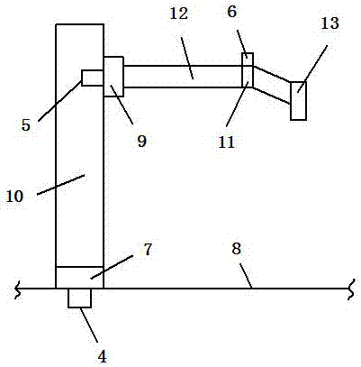
[0032] refer to Figure 1-2 , a specific embodiment of the present invention includes,

[0033] An image processing module 1, configured to process scanned images;

[0034] The electronic control module 2 controls the drive module 3 by collecting the processing results of the image processing module 1;

[0035] The drive module 3 includes a transverse drive motor 4, a longitudinal drive motor 5 and a 180° rotation motor 6;

[0036] The transverse drive motor 4 is used to drive the transverse slider 7, and the transverse slider 7 is slidably arranged in the transverse slide rail 8;

[0037] The longitudinal...


PUM


Abstract

The invention discloses a laser positioning puncture navigation device. The device comprises an image processing module, an electronic control module, a drive module and a laser output module, wherein the image processing module is used for processing a scan image; the electronic control module is used for controlling the driver module by collecting processing results of the image processing module; the driver module comprises a horizontal driving motor, a longitudinal driving motor and a 180-degree rotation motor; the horizontal driving motor is used for driving a horizontal sliding block which is arranged in a horizontal sliding rail in a sliding mode; the longitudinal driving motor is used for driving a longitudinal sliding block which is arranged in a longitudinal sliding rail in a sliding mode, and the longitudinal sliding rail is fixed to the horizontal sliding block; the 180-degree rotation motor is used for driving a 180-degree rotational joint which is arranged on the longitudinal sliding block through a support rod; the laser output module is connected with the 180-degree rotational joint and used for outputting a laser and indicating on the puncture direction. The invention further discloses a puncture positioning method of the laser positioning puncture navigation device. The laser positioning puncture navigation device can overcome the shortages of the prior art and improve the puncture precision.

Description

technical field [0001] The invention relates to the technical field of medical devices, in particular to a laser positioning puncture navigation device and a puncture positioning method thereof. Background technique [0002] With the development of medical technology, minimally invasive diagnosis and treatment under the guidance of CT or MCR are more and more widely used. The key to this diagnosis and treatment technology is precise puncture, which mainly involves the angle and depth of the puncture needle, and the angle is often a relatively large Difficult to control factors, so the main factor affecting the accuracy of puncture is the needle insertion angle of the puncture needle. Most hospitals complete the manual operation based on experience. Since the needle insertion angle of the puncture needle is a three-dimensional space angle, the pure experience operation is successful once. The rate is low and repeated adjustments are required, which not only prolongs the opera...

Claims


Application Information

Patent Timeline
Patent Type & Authority Applications(China)
IPC IPC(8): A61B17/34A61B34/20A61B34/10
CPCA61B17/3403
Inventor 叶欣孙良俊
Owner NANJING ECO MICROWAVE SYST
Learn More