A fire escape and rescue system for high-rise buildings

A high-rise building and firefighting technology, applied in the field of fire escape rescue systems, can solve the problems of suffocation of escape personnel, inability of escape personnel to reach the fire escape layer in a safe and timely manner, congestion or stampede of people, etc.

Active Publication Date: 2020-08-04
昆明理工泛亚设计集团有限公司
View PDF8 Cites 0 Cited by
  • Summary
  • Abstract
  • Description
  • Claims
  • Application Information

AI Technical Summary

Problems solved by technology

High-rise buildings have high fire protection requirements and difficult fire fighting. Once a fire breaks out, the fire will spread quickly, and it will be difficult to evacuate people and fire fighting.
[0003] At present, the main fire escape channel relies on the fire stairs, and the evacuees are evacuated from the fire stairs. However, when there are too many people, congestion or stampede incidents have occurred. If there is smoke in the fire stairs, the escape personnel may inhale a large amount of smoke during their strenuous activities. Gas, causing suffocation or coma of escaped persons
High-rise buildings with a height of more than 100 meters will be equipped with fire refuge floors. When a fire comes, escapers can go to the fire refuge floors to take refuge. However, there are often 15 floors between fire refuge floors. When the fire situation is critical, escape personnel often cannot safely Arrive at the fire refuge floor in time
At present, the working height of domestic fire trucks is up to 50m, which cannot meet the higher and higher building heights. Once a fire occurs on a too high floor, firefighters need to carry fire fighting equipment to climb up from the safety ladder, which greatly affects the progress of fire fighting.

Method used


Image

  • A fire escape and rescue system for high-rise buildings
  • A fire escape and rescue system for high-rise buildings
  • A fire escape and rescue system for high-rise buildings

Examples


Embodiment 1

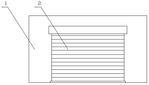
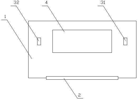
[0026] refer to Figure 1-3 , figure 1 A schematic diagram of a fire house for a fire escape and rescue system for high-rise buildings provided by the present invention; figure 2 It is a top view diagram of a fire house of a fire escape rescue system for a high-rise building provided by the present invention; image 3 It is a schematic cross-sectional view of a fire house for a fire escape and rescue system for high-rise buildings provided by the present invention.

[0027] Specifically, a fire escape and rescue system for high-rise buildings includes a fire house 1 arranged on each floor of a high-rise building, and the fire house 1 includes a closed gate 2, a cableway 3, and a ground passage 4; the ground passage 4 is set On the ground of the fire house 1, the ground passage 4 of each fire house 1 is at the same position; the cableway 3 includes an upper fixed station 31 and a lower fixed station 32, and the upper fixed station 31 is arranged on one side of the ground pas...

Embodiment 2

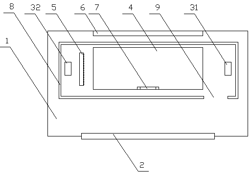
[0035] refer to Figure 4-5 , Figure 4It is a top view schematic diagram of the fire house of the second fire escape and rescue system for high-rise buildings provided by the present invention; Figure 5 It is a schematic cross-sectional view of the fire house of the second fire escape and rescue system for high-rise buildings provided by the present invention.

[0036] This embodiment is basically the same as the first embodiment, except that an anti-collision wall 5 is provided between the lower fixing frame and the ground passage 4 .

[0037] As a preferred mode of the present invention, the fire house 1 is connected to the exterior wall of the building, and the fire house 1 part of the exterior wall of the building is provided with tempered glass 6, and the tempered glass 6 is only broken when struck by sharp objects.

[0038] As a preferred mode of the present invention, the ground passage 4 is also provided with a fixed ladder 7, and the two ends of the fixed ladder 7...

Embodiment 3

[0047] refer to Figure 6 , Figure 6 It is a top view schematic diagram of the fire house of the third fire escape and rescue system for high-rise buildings provided by the present invention.

[0048] As a preferred form of the present invention, the fire house 1 is provided with a water storage tank 10, and the water storage tank 10 contains pre-stored water.

[0049] As a preferred form of the present invention, the fire house 1 is provided with an independent power supply unit 11 , the slide rope 33 is connected to the independent power supply unit 11 , and the slide rope 33 goes up when the independent power supply unit 11 supplies power.

[0050] Wherein, the fire house 1 is provided with a water storage tank 10, the water stored in the water storage tank 10 prevents the water pipe from breaking, and the water storage tank 10 is also used for cooling the closed gate 2, when the closed gate 2 is overheated The water in the water storage tank 10 can be used to cool down ...


PUM


Abstract

The invention relates to a fire-fighting escape and rescue system for a high-rise building. The fire-fighting escape and rescue system for the high-rise building comprises a fire-fighting room arranged on each floor of the high-rise building, each fire-fighting room comprises a closed gate, a cableway, and a ground channel; the ground channel is arranged on the ground of the fire-fighting room, and the ground channel of each fire-fighting room is arranged in the same position; the cableway comprises an upper fixed station and a lower fixed station, the upper fixed station is arranged on the side of the ground channel, and the lower fixed station is arranged on the other side of the ground channel on the lower floor corresponding to the ground channel on the upper floor; the cableway further comprises a strop roadway, the strop roadway is provided with a plurality of lifting slings, and the lifting slings are fixed to each other through tow ropes; the cableway is provided with a reduction gear used for helping the lifting slings lower sliding speed in the descent process; and the closed gate is arranged at the entrance of the fire-fighting room, is normally in a closed state and cannot be opened, and is connected with a fire alarm, and when the fire alarm is triggered, the closed state of the closed gate is end.

Description

technical field [0001] The invention relates to a fire-fighting system for high-rise buildings, in particular to a fire-fighting, escape and rescue system for high-rise buildings. Background technique [0002] Fire is most often. One of the most common major disasters that threaten public safety and social development. With the rapid development of cities, high-rise residential buildings are increasing year by year, bringing vigor and vitality to modern cities, but at the same time bringing new challenges to fire safety. question. High-rise buildings have high fire protection requirements and difficult fire fighting. Once a fire breaks out, the fire will spread quickly, make it difficult to evacuate people, and make fire fighting difficult. [0003] At present, the main fire escape channel relies on fire stairs, and the evacuees are evacuated from the fire stairs. However, when there are too many people, congestion or stampede incidents have occurred. If there is smoke in ...

Claims


Application Information

Patent Timeline
Patent Type & Authority Patents(China)
IPC IPC(8): A62B1/06E06C9/02
CPCA62B1/06E06C9/02
Inventor 李伟阮云坤赵伟吴静
Owner 昆明理工泛亚设计集团有限公司
Why Eureka
Try Eureka