
Shaft sleeve external diameter measuring and sorting device

The technology of a sorting device and a shaft sleeve is applied in the field of the outer diameter measurement and sorting device of the shaft sleeve, which can solve the problems of reduced automation, troublesome operation, high labor intensity of workers, etc., and achieves the effects of efficient and accurate measurement and simple structure.

Inactive Publication Date: 2017-08-22
张雅婷
View PDF0 Cites 1 Cited by
  • Summary
  • Abstract
  • Description
  • Claims
  • Application Information

AI Technical Summary

Problems solved by technology

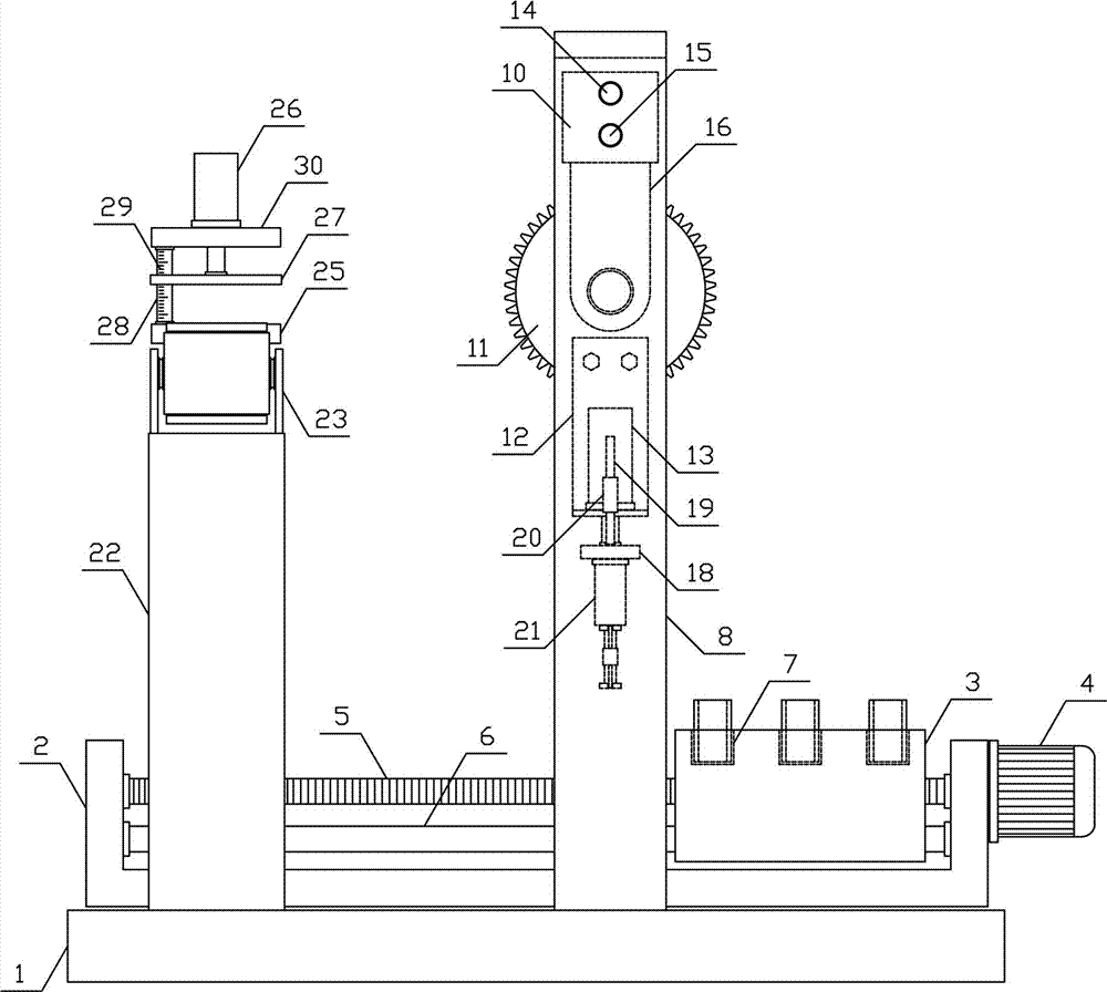
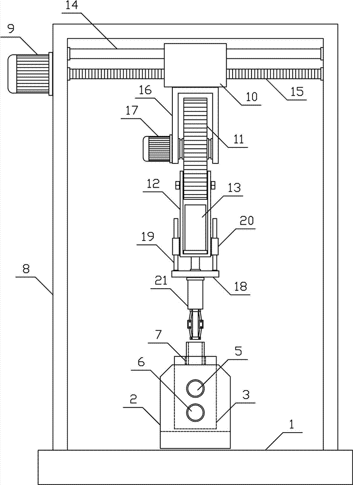
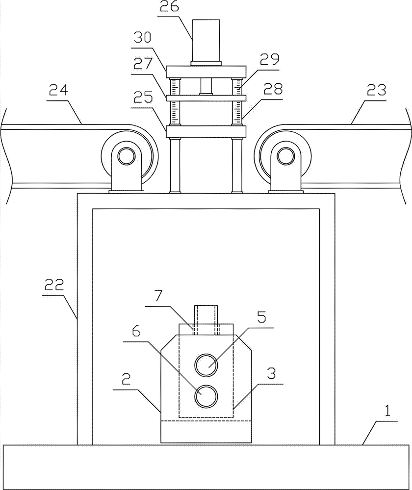
During the production and processing of the existing shaft sleeves, it is necessary to carry out quality inspection on the finished shaft sleeves. During the quality inspection, the shaft sleeves need to carry out multiple inspections, including the detection of the size specifications of the shaft sleeves. The outer diameter of the shaft sleeve needs to be detected during the detection of the size specification of the shaft sleeve. In the detection process of the shaft sleeve, the shaft sleeve is generally manually detected by using a measuring ruler. The detection efficiency of the shaft sleeve is low and the labor intensity of the workers is high. And it is easy to generate large errors in the detection process of the shaft sleeve, which makes it difficult to efficiently and accurately sort a large number of shaft sleeves. The existing shaft sleeve outer diameter measurement mechanism has a complex structure and troublesome operation. During the process, it is necessary to manually place the sleeves one by one in the measuring mechanism for outer diameter measurement, and manually sort the measured sleeves. The automation of the entire production process of the sleeves is greatly reduced, and the production efficiency of the sleeves is difficult to be guaranteed. Can not meet the needs of production use

Method used


Image

  • Shaft sleeve external diameter measuring and sorting device
  • Shaft sleeve external diameter measuring and sorting device
  • Shaft sleeve external diameter measuring and sorting device

Examples


Embodiment Construction

[0012] In order to further describe the present invention, a specific implementation of a sleeve outer diameter measuring and sorting device is further described below with reference to the accompanying drawings. The following examples are for explaining the present invention and the present invention is not limited to the following examples.

[0013] Such as figure 1 As shown, the sleeve outer diameter measuring and sorting device of the present invention includes a fixed base 1, a sleeve conveying mechanism, a sleeve feeding mechanism, and a measuring and sorting mechanism. The sleeve conveying mechanism is horizontally arranged on the upper middle of the fixed base 1. The sleeve feeding mechanism and the measuring and sorting mechanism are vertically arranged on the upper two sides of the fixed base 1 in sequence along the conveying direction of the shaft sleeve. The shaft sleeve conveying mechanism of the present invention includes a translation base 2, a conveying bracket 3 a...


PUM


Abstract

The invention discloses a measuring and sorting device for the outer diameter of a shaft sleeve, which belongs to the field of mechanical product processing auxiliary equipment. The invention package includes a fixed base, a shaft sleeve conveying mechanism, a shaft sleeve feeding mechanism, and a measuring and sorting mechanism. The bracket is slid and installed on the translation guide rod along the horizontal direction, and the upper side of the conveying bracket is vertically and uniformly arranged with a plurality of shaft sleeves in order along the direction of the translation guide rod. The finished product transmission mechanism and the defective product transmission mechanism are arranged horizontally and symmetrically on the upper two sides respectively, and the pressing measuring plate is slid on the measuring rod along the vertical direction. The invention has a reasonable structural design, can quickly and conveniently transport and measure the shaft sleeves one by one, and can efficiently sort the measured shaft sleeves to meet the needs of production and use.

Description

Technical field [0001] The invention belongs to the field of mechanical product processing auxiliary equipment, and in particular relates to a shaft sleeve outer diameter measuring and sorting device. Background technique [0002] The shaft sleeve is a cylindrical mechanical part sleeved on the rotating shaft. It is an integral part of the sliding bearing. The shaft sleeve and the bearing seat adopt an interference fit, and the shaft adopts a clearance fit. The shape of the sleeve is a complete cylinder. In the production and processing of the existing bushings, the finished bushings need to be inspected. The quality inspection of the bushings needs to be inspected for multiple items, including inspections for the size and specifications of the bushings. In the process of detecting the size of the shaft sleeve, the outer diameter of the shaft sleeve needs to be detected. The shaft sleeve is generally manually inspected with a measuring rule during the detection process. The detec...

Claims


Application Information

Patent Timeline
Patent Type & Authority Applications(China)
IPC IPC(8): B07C5/34B07C5/02B07C5/36
CPCB07C5/34B07C5/02B07C5/362
Inventor 张雅婷
Owner 张雅婷
Learn More