
Lifting workbench

A technology for lifting and lowering workbenches and working platforms, which is applied in the direction of workbenches and manufacturing tools, can solve the problems of heavy equipment, narrow scope of application, difficult handling and adjustment of positions, etc., to meet the needs of processing and use, reasonable structural design, and increase the scope of application Effect

Inactive Publication Date: 2017-08-22
钟彩凤
View PDF0 Cites 11 Cited by
  • Summary
  • Abstract
  • Description
  • Claims
  • Application Information

AI Technical Summary

Problems solved by technology

The existing workbench can be lifted and lowered according to the needs of use during use, but the existing workbench is generally driven by a hydraulic cylinder or an air cylinder, so the workbench needs to be equipped with ancillary equipment such as an air source or a hydraulic press during use , high energy consumption and heavy equipment quality, it is difficult to conveniently carry and adjust the position according to the needs during use, and the existing working platform can only be lifted and lowered according to the needs, and it is difficult to rotate according to the needs of normal processing to make the platform tilt. The scope of application is narrow and cannot meet the needs of use

Method used


Image

  • Lifting workbench
  • Lifting workbench

Examples


Embodiment Construction

[0011] In order to further describe the present invention, a specific implementation of a lifting workbench will be further described below in conjunction with the accompanying drawings. The following examples are explanations of the present invention and the present invention is not limited to the following examples.

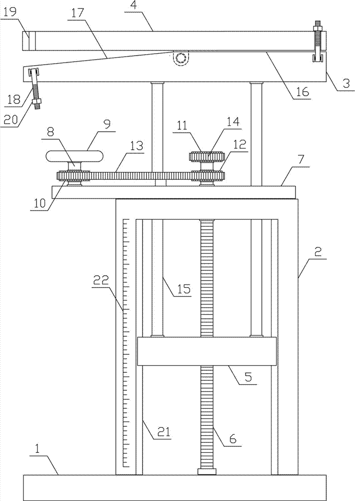
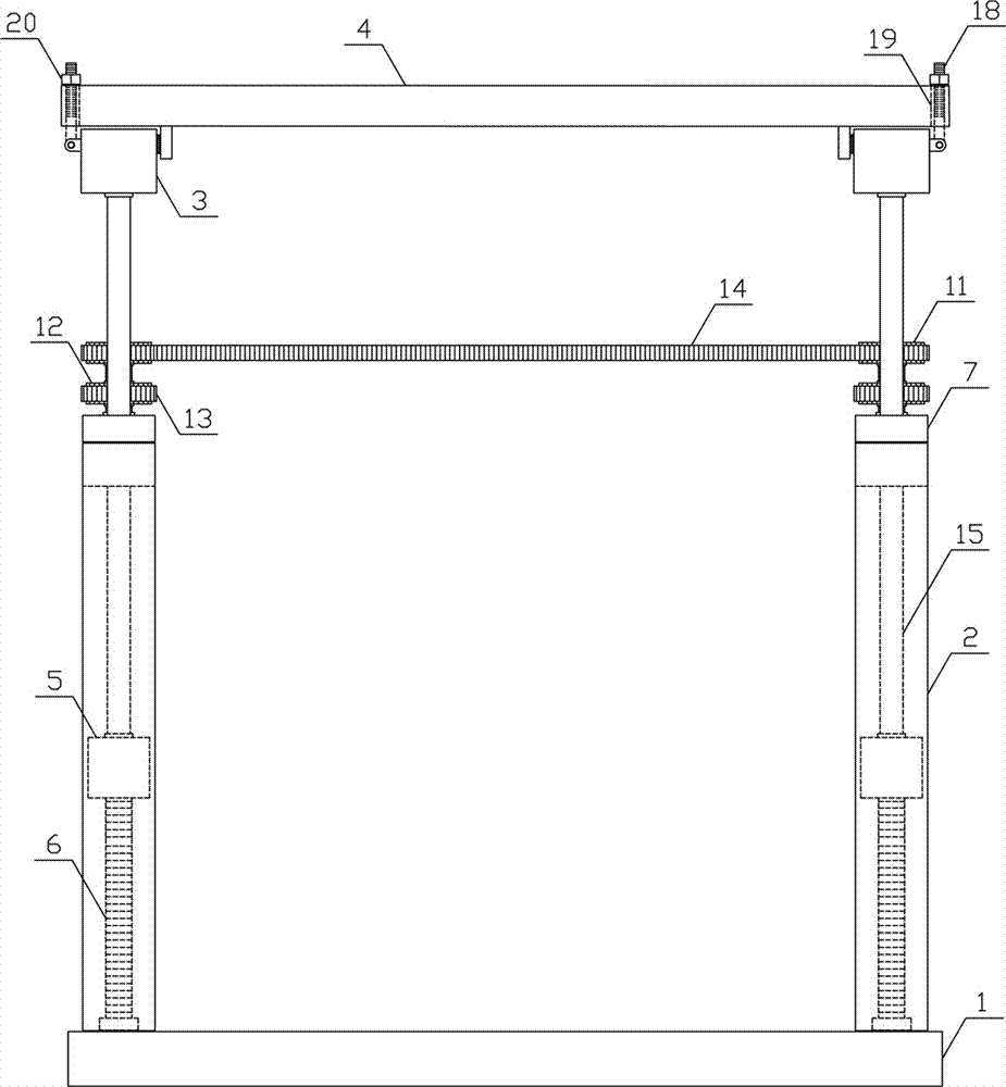
[0012] Such as figure 1 , figure 2 As shown, an elevating workbench of the present invention includes a fixed base 1, an adjustment bracket 2, a bearing plate bracket 3 and a working platform 4, and the two sides above the fixed base 1 are respectively vertically and symmetrically provided with an adjustment bracket 2, and the upper edge of the adjustment bracket 2 A lifting plate 5 is slidably arranged in the vertical direction, and the middle part of the adjustment bracket 2 is vertically rotated to be connected with an adjustment screw 6, and the adjustment screw 6 is threadedly connected to the lifting plate 5, and the upper side of the adjustment bracket ...


PUM


Abstract

The invention provides a lifting workbench, and belongs to the field of machining auxiliary mechanical equipment. The lifting workbench comprises a fixed base, adjusting supports, bearing plate supports and a working platform. The adjusting supports are vertically and symmetrically arranged on the two sides of the top of the fixed base, and a lifting plate is arranged on the adjusting supports in a sliding mode in the vertical direction. Two synchronous chain wheels on the two sides of the top of the fixed base are connected in a transmission mode through a synchronous chain. The bearing plate supports are horizontally arranged at the upper ends of lifting guide rods, the working platform is horizontally arranged on the upper sides of the bearing plate supports, and the middle portions of the two sides of the bottom of the working platform are hinged to the middle portions of the bearing plate supports on the two sides of the top of the fixed base respectively. Locking lead screws are arranged on one side of one bearing plate support and the other side of the other bearing plate support, and locking clamping grooves which are matched with the locking lead screws are formed in the outer side of the working platform. The lifting workbench is reasonable in structural design, can rapidly and stably conduct horizontal ascent and descent on the working platform, can conduct rotating adjustment and fixing on the working platform as required, and meets the requirement of machining utilization.

Description

technical field [0001] The invention belongs to the field of processing auxiliary mechanical equipment, and in particular relates to a lifting workbench. Background technique [0002] The workbench is an important auxiliary equipment in modern industry. It is generally made of high-quality plates and has a wide range of uses. The workbench is suitable for various applications such as molds, fitters, testing, maintenance and assembly. It has good Excellent corrosion resistance, dirt resistance, impact resistance and load-bearing capacity, the workbench is divided into inspection platform, marking platform, boring and milling machine platform and welding platform according to the purpose. The existing workbench can be lifted and lowered according to the needs of use during use, but the existing workbench is generally driven by a hydraulic cylinder or an air cylinder, so the workbench needs to be equipped with ancillary equipment such as an air source or a hydraulic press durin...

Claims


Application Information

Patent Timeline
IPC IPC(8): B25H1/16
CPCB25H1/16
Inventor 钟彩凤
Owner 钟彩凤
Learn More