
Riveting robot with real-time monitoring function

A real-time monitoring and robotic technology, applied in the direction of program control manipulators, manipulators, manufacturing tools, etc., can solve the problem that the riveting work cannot be guaranteed to run efficiently and stably for a long time, the working status of the locking claw head cannot be monitored in real time, and the rivet locking is prone to interference. and other problems, to achieve the effect of convenient and fast feeding, significant alarm prompt effect, and improved safety and accuracy.

Inactive Publication Date: 2017-08-22
TAICANG WEIGUAN ELECTROMECHANICAL
View PDF6 Cites 3 Cited by
  • Summary
  • Abstract
  • Description
  • Claims
  • Application Information

AI Technical Summary

Problems solved by technology

[0005] 1. The overall safety is poor, and it cannot respond in time when an unexpected situation occurs, and cannot guarantee the long-term efficient and stable operation of the riveting work;
[0006] 2. The overall size and weight of the robot is large, and it cannot move flexibly in the workshop. The production and operation costs are high, and the service life is short;
[0007] 3. The staff cannot monitor the specific working status of the locking claw head in real time, so deviations are prone to occur during riveting;
[0008] 4. It is easy to have interference problems when rivets are locked and paid, and the work stability is poor

Method used


Image

  • Riveting robot with real-time monitoring function

Examples


Embodiment 1

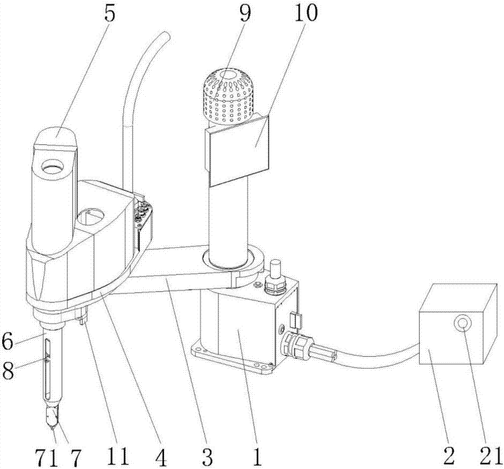
[0027] Such as figure 1 As shown, a riveting robot with real-time monitoring function in this embodiment includes a base 1, a controller 2, a first articulated arm 3, a second articulated arm 4, an air motor 5, a connecting sleeve 6, and a locking claw head 7. Vacuum suction nozzle 71, suction head assembly 8, sonar sensor 9, display screen 10, CCD camera 11 and automatic alarm device 21.

[0028] The connection relationship of the above-mentioned components is as follows: the first articulated arm 3 is installed on the base 1, the second articulated arm 4 is installed on the first articulated arm 3, the first articulated arm 3 and the second articulated arm 4 Both are driven by an AC torque motor; the air motor 5 and the connecting sleeve 6 are installed on the second articulated arm 4, and the connecting sleeve 6 is provided with a suction head assembly 8 and a screw, and the screw rod is connected with the air motor 5 up and down respectively. , the locking claw head 7 is ...


PUM


Abstract

The invention discloses a riveting robot with a real-time monitoring function, and relates to the technical field of intelligent manufacturing. A pneumatic motor and a connecting sleeve are both installed on a second joint arm, a suction head assembly and a screw are arranged inside the connecting sleeve, the upper portion and the lower portion of the screw are connected with the pneumatic motor and a locking claw head in a matched manner, and the screw is driven by a hollow shaft motor connected with the screw; the suction head assembly is connected with the locking claw head and a vacuum suction nozzle, and a riveting head is connected to the bottom of the vacuum suction nozzle; a base is connected with an external controller, and an automatic alarm device is arranged on one side of the controller; a CCD camera connected with a display screen is arranged at the bottom of a second joint arm; and the surfaces of the base, the first joint arm and the second joint arm are provided with protection layers, and the surface of the connecting sleeve is coated with a self-light-emitting layer. The robot is good in safety and stability, a worker can monitor the working state in real time, the service life is long, cost is low, and it is guaranteed that the riveting work is done efficiently and stably for a long time.

Description

technical field [0001] The invention relates to the technical field of intelligent manufacturing, in particular to a riveting robot with real-time monitoring function. Background technique [0002] In recent years, with the acceleration of modernization, the demand for electrical products and home appliances has been increasing, and the mechanized and automated production and assembly lines have increased greatly. The method is far from being able to adapt to the needs of mechanization and automation mass production and assembly. Therefore, how to solve the problem of high-speed screw locking and improve the quality and consistency of locking has become a subject of great concern to those skilled in the art. [0003] In order to solve this problem, many manufacturers have developed a variety of riveting robots, the main feature of which is that there is a rivet supply device that blows the rivets into a left and right openable elastic jaws under the screwdriver head. The p...

Claims


Application Information

Patent Timeline
Patent Type & Authority Applications(China)
IPC IPC(8): B25J9/04B25J11/00B25J15/06
CPCB25J15/0675B25J9/044B25J11/007B25J15/0616
Inventor 张俊骁
Owner TAICANG WEIGUAN ELECTROMECHANICAL
Learn More