Positioning method for non-reflector laser navigation by adopting auxiliary

A technology of laser navigation and positioning method, applied in directions such as ground navigation, can solve the problems of not meeting the requirements of use and the reduction of laser beam accuracy, and achieve the effect of improving positioning accuracy

Inactive Publication Date: 2017-08-22
SUZHOU AGV ROBOT CO LTD
View PDF8 Cites 1 Cited by
  • Summary
  • Abstract
  • Description
  • Claims
  • Application Information

AI Technical Summary

Problems solved by technology

Although it can meet most of the application occasions, due to the characteristics of the laser beam in the long-distance reflection, the accuracy drops, etc., in some occasions with high precision requirements, it cannot meet the use requirements.

Method used


Image

  • Positioning method for non-reflector laser navigation by adopting auxiliary

Examples


Embodiment Construction

[0021] The present invention discloses a non-reflective plate laser navigation positioning method using auxiliary objects. In the non-reflective plate laser navigation system, auxiliary objects are set on specific workstations with accuracy requirements, combined with relevant data of the mobile platform, Then calculate and correct the pose of the mobile platform in real time. Specifically include the following steps.

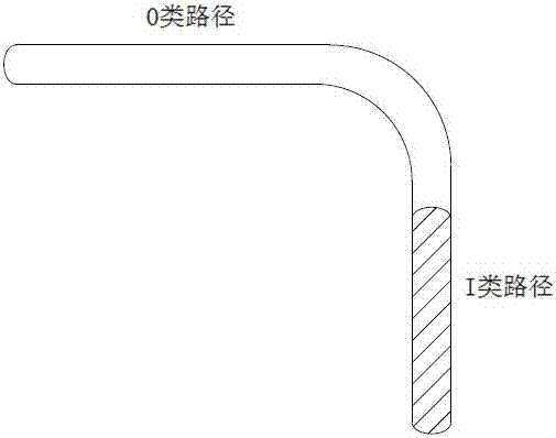
[0022] S1. The navigation path of the non-reflective laser navigation system is defined as a category 0 path, and a category I path with different color differences from the ground is set on a road section with accuracy requirements; the category I path with different color differences is obtained by laying ribbons or painting, The width is 15-25mm.

[0023] S2. The visual sensor installed on the mobile platform of the non-reflective laser navigation system, shoots the type I path at a certain frequency, and obtains the offset between the center line of the vision ...


PUM


Abstract

The invention discloses a positioning method for non-reflector laser navigation by adopting an auxiliary. The method comprises the following steps: a navigation path of a non-reflector laser navigation system is defined as a 0 type path and a I type path which is of different aberration with the ground is arranged in a section with precision requirement; a visual sensor mounted on a mobile platform of the non-reflector laser navigation system photographs the I type path at a certain frequency to acquire an offset distance from a central line of the visual sensor to a central line of the I type path, that is, the transverse deviation h of the mobile platform; and when the mobile platform travels on the I type path, the mobile platform acquires a deflection angle alpha of the mobile platform and a real-time distance I of longitudinal movement through the non-reflector laser navigation system, and calculates accurate real-time posture information according to h, alpha and l so as to correct the posture of the mobile platform in real time. According to the positioning method disclosed by the invention, in a station which is relatively high in precision demand, stable coordinate information is formed by adding a local auxiliary label and combining with a non-reflector laser technology, so that the positioning precision is greatly improved and the precision is stably kept at +/-10mm.

Description

Technical field [0001] The invention relates to a non-reflective plate laser navigation positioning method using auxiliary objects. Background technique [0002] The non-reflective laser navigation technology is being applied in more and more fields because of its characteristics such as no need to lay reflectors and suitable for long-distance transportation. Although it can meet most of the application occasions, due to the characteristics of reduced accuracy of the laser beam during long-distance reflection, it cannot meet the requirements of use in some occasions with high accuracy requirements. Summary of the invention [0003] The purpose of the present invention is to provide a positioning method for non-reflective plate laser navigation using auxiliary objects. In some stations with high precision requirements of non-reflective plate laser navigation, by adding local auxiliary markers, and non-reflective plate laser Combining technologies to form stable coordinate informat...

Claims


Application Information

Patent Timeline
Patent Type & Authority Applications(China)
IPC IPC(8): G01C21/04
Inventor 司秀芬刘胜明万福平
Owner SUZHOU AGV ROBOT CO LTD
Why Eureka
Try Eureka