

Navigation method and device
A azimuth and target position technology, applied in the field of navigation methods and devices, can solve problems such as large limitations, and achieve the effect of reducing limitations
- Summary
- Abstract
- Description
- Claims
- Application Information
AI Technical Summary
Problems solved by technology
Method used
Image

Examples
Embodiment 1
[0049] The embodiment of the present invention provides a navigation method.
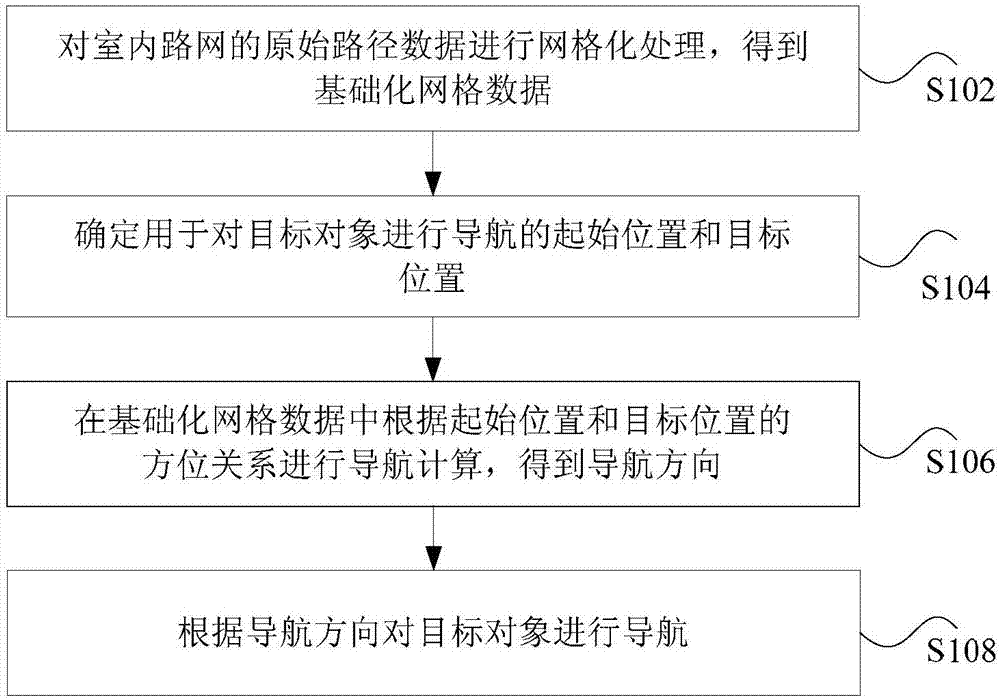
[0050] figure 1 is a flowchart of a navigation method according to an embodiment of the present invention. Such as figure 1 As shown, the navigation method includes the following steps:
[0051] Step S102, performing grid processing on the original path data of the indoor road network to obtain basic grid data.
[0052] In the technical solution provided by the above step S102 of the present invention, grid processing is performed on the original path data of the indoor road network to obtain basic grid data.
[0053] In the indoor environment, the original route data of the indoor road network is obtained, and the original route data includes information of each location in the indoor road network. After the original path data is obtained, the grid processing of the original path data is different from the traditional navigation method which adopts the concept of connected graph in graph theory...
Embodiment 2
[0107] The technical solutions of the present invention will be described below in conjunction with preferred embodiments.
[0108] The embodiment of the present invention relates to the establishment of a navigation road network model based on an earth space grid and a navigation method based on the road network model. Firstly, the use of navigation grid and two-dimensional code technology to determine the navigation position information and orientation is proposed, which can solve the problem that the current indoor navigation cannot use traditional navigation methods, thus making up for the vacancy of indoor application of navigation and path search.
[0109]In order to achieve the above purpose, the embodiment of the present invention uses the navigation grid and the two-dimensional code technology to determine the navigation position information and the guidance navigation method of the azimuth pointing, and preprocess the original indoor route data into a grid to obtain t...
Embodiment 3
[0130] The technical solution of the present invention will be described below in combination with optional embodiments.
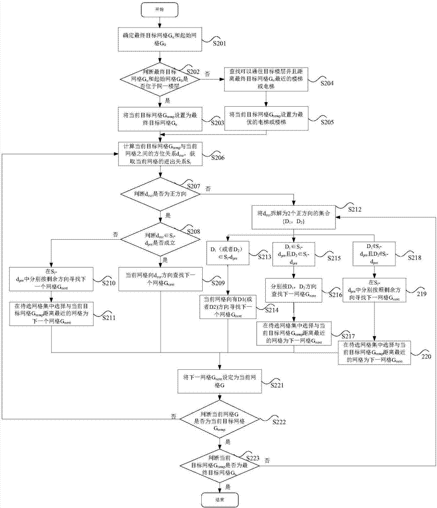
[0131] figure 2 is a flowchart of another navigation method according to an embodiment of the present invention. Such as figure 2 As shown, the method includes the following steps:
[0132] Step S201, determine the final target grid G n and the starting grid G 0 .
[0133] Step S202, determine the final target grid G n and the starting grid G 0 Are they on the same floor.
[0134] In determining the final target grid G n and the starting grid G 0 After that, determine the final target grid G n and the starting grid G 0 Whether it is on the same floor, if it is judged that the final target grid G n and the starting grid G 0 Located on the same floor, execute step S203, if it is judged that the final target grid G n and the starting grid G 0 If they are not on the same floor, go to step S204.
[0135] Step S203, the current target grid G t...
PUM
 Abstract
Description
Claims
Application Information