Electronic control light adjusting film based on liquid crystal and dichroic dye and preparing method thereof

A dichroic, light-adjustable film technology, applied in the field of optical polarization, can solve the problem that the anti-peep film cannot be switched, and achieve the effects that the anti-peep performance can be electronically adjusted, the preparation method is simple, and the light transmittance will not be affected.

Active Publication Date: 2017-08-22
PEKING UNIV
View PDF6 Cites 23 Cited by
  • Summary
  • Abstract
  • Description
  • Claims
  • Application Information

AI Technical Summary

Problems solved by technology

[0004] The purpose of the present invention is to overcome the defect that the existing anti-peeping film cannot be switched between the

Method used


Image

  • Electronic control light adjusting film based on liquid crystal and dichroic dye and preparing method thereof
  • Electronic control light adjusting film based on liquid crystal and dichroic dye and preparing method thereof
  • Electronic control light adjusting film based on liquid crystal and dichroic dye and preparing method thereof

Examples


Embodiment 1

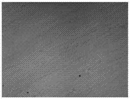
[0043]First, wash the PET substrate coated with ITO film with detergent and warm water, remove the particles, dust and impurities of the PET substrate, then wash it with acetone solution, and spin-coat a layer of PVA orientation on the PET substrate coated with ITO film. agent, cured at high temperature (110°C) for 2 hours, and carried out rubbing orientation. Next, after mixing the photopolymerizable liquid crystal monomer, DD molecules, NLC molecules, photoinitiators, and spacer particles evenly, the mixed solution is sandwiched between two layers of transparent ITO plastic conductive films, and then pressed into a film by pressing rollers. When it is shown in Figure 3(a). Then, as shown in Figure 3(b), by irradiating the film with ultraviolet (UV) light through a mask, the UV light passing through the mask triggers a cross-linking reaction between the photopolymerizable monomer molecules to form a photopolymerizable liquid crystal network , NLC, and DD composite material r...

Embodiment 2

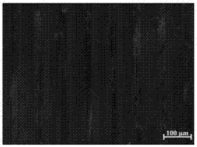
[0046] First, wash the PET substrate coated with ITO film with detergent and warm water, remove the particles, dust and impurities of the PET substrate, then wash it with acetone solution, and spin-coat a layer of PVA orientation on the PET substrate coated with ITO film. agent, cured at high temperature (110°C) for 2 hours, and then carried out rubbing orientation. Next, after mixing the photopolymerizable liquid crystal monomer, DD molecules, N*LC molecules, photoinitiators, and spacer particles evenly, the mixture is sandwiched between two layers of transparent ITO plastic conductive films, and then pressed into a film by pressing rollers , as shown in Figure 4(a). Then, as shown in Figure 4(b), by irradiating the film with ultraviolet (UV) light through a mask, the UV light passing through the mask triggers a cross-linking reaction between the molecules of the photopolymerizable liquid crystal monomer to form a photopolymerizable liquid crystal The network, N*LC, and DD c...


PUM

PropertyMeasurementUnit
Widthaaaaaaaaaa
Thicknessaaaaaaaaaa

Abstract

The invention relates to an electronic control light adjusting film based on liquid crystal and dichroic dye. The film comprises a first transparent indium tin oxide plastic conductive film layer, a composite material film layer and a second transparent indium tin oxide plastic conductive film layer; the composite material film layer comprises liquid crystal molecules, dichroic dye molecules and a macromolecule network, wherein a first composite material region is formed by the liquid crystal molecules and the dichroic dye molecules, a second composite material region is formed by the liquid crystal molecules, the dichroic dye molecules and the macromolecule network, and the first composite material region and the second composite material region are alternately arrayed in the composite material film layer in the direction perpendicular to incident light in a periodicity mode. The electronic control light adjusting film has the advantage that the angle range of transmission light can be adjusted. The electronic control light adjusting film is hopeful to be applied to display devices, and an electric field is opened and closed so that the display devices can be switched between a peeping preventing state and a non-peeping preventing state.

Description

technical field [0001] The invention relates to the technical field of optical polarization, in particular to an electrically controlled dimming film based on liquid crystals and dichroic dyes and a preparation method thereof. Background technique [0002] Nowadays, electronic products have been integrated into people's life and work, and provide people with a lot of convenience. However, due to the large viewing angle of the liquid crystal display, when the information of electronic products is browsed by the user himself, it is very easy to Being peeped by the side, for some commercial and military secrets and personal privacy, people don't want to be peeped by the side. [0003] The 3M company of the United States took the lead in developing the anti-peeping film with an ultra-fine louver (MICROLOVER) structure. figure 1 It is a schematic diagram of the principle of the anti-spy film. As shown in the figure, the anti-spy film includes in order from top to bottom: PET lay...

Claims


Application Information

Patent Timeline
IPC IPC(8): G02F1/1334G02F1/137
CPCG02F1/1334G02F1/13718G02F1/13737G02F1/13345
Inventor 杨槐周乐马海鹏韩城胡威张兰英
Owner PEKING UNIV
Why Eureka
Try Eureka