Construction positioning method for cable duct at spatial beam end of full framing

A technology of full house support and positioning method, which is applied in the erection/assembly of bridges, bridges, bridge construction, etc., can solve the problems of inability to guarantee the installation accuracy of the central axis of the cable guide, difficult to meet the positioning accuracy requirements, and affecting the service life of the cable guide. Achieve the effect of saving installation time, simple structure, saving manpower and material resources

Active Publication Date: 2017-08-25
CCCC SECOND HARBOR ENG
View PDF7 Cites 11 Cited by
  • Summary
  • Abstract
  • Description
  • Claims
  • Application Information

AI Technical Summary

Problems solved by technology

Since its positioning accuracy is largely affected by the processing errors of pipe fittings or other components, it is difficult to meet its positioning accuracy requirements
There is no reference object when moving the cable guide, and it can only be judged by experience, which requires repeated measurement, repeated fixing and unfastening, poor accuracy and low efficiency
[0003] In the Chinese utility model patent specification CN 205604090U, a cable-stayed bridge space cable guide positioning device is disclosed, including a front frame, a rear frame, and an upper cross bar and a lower cross bar for connecting the front frame and the rear frame into an integral frame; A diagonal brace for supporting the cable conduit is provided between the front frame and the lower cross bar, and the angle between the plane where the diagonal brace is located and the horizontal plane is 26.0°-72.0°; the space cable conduit positioning device for the cable-stayed bridge of the invention , although the cable guide can be accurately positioned and reinforced before the reinforcement is installed, it cannot guarantee the installation accuracy of the central axis of the cable guide. Affect the service life of the cable guide

Method used


Image

  • Construction positioning method for cable duct at spatial beam end of full framing
  • Construction positioning method for cable duct at spatial beam end of full framing
  • Construction positioning method for cable duct at spatial beam end of full framing

Examples


Embodiment Construction

[0021] The preferred embodiments of the present invention will be described below in conjunction with the accompanying drawings. It should be understood that the preferred embodiments described here are only used to illustrate and explain the present invention, and are not intended to limit the present invention.

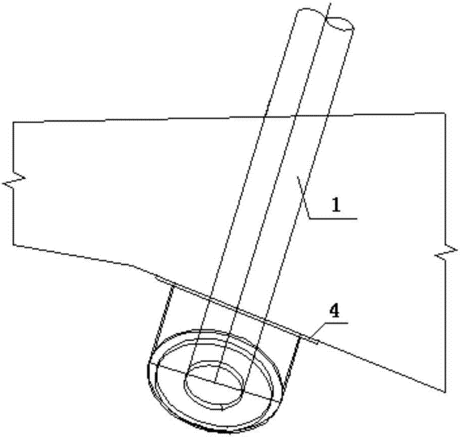
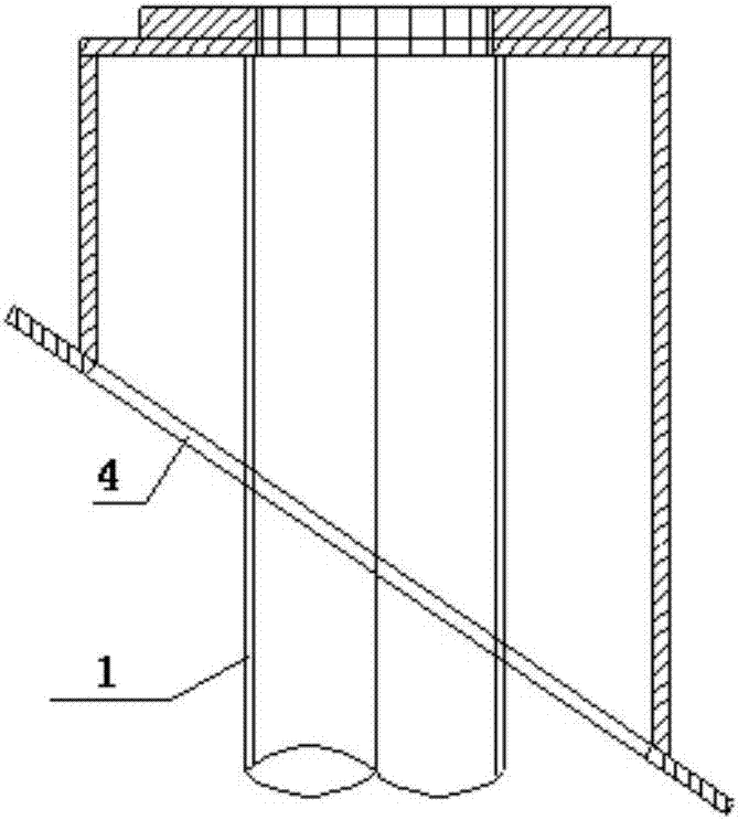
[0022] It can be known from the accompanying drawings of the invention description that the present invention provides a construction positioning method for the beam end cable guide in the space of the full hall support. And the auxiliary disc 4 used for checking the anchor point of the lower port of the cable conduit 1; the top port positioning device 3 is fixedly connected to the positioning bracket 2; the top port positioning device 3 includes a first positioning member 3.1 fixed on the upper end surface of the positioning bracket 2 , the second positioning member 3.2 fixed to the side end surface of the positioning bracket 2 and the third positioning member 3.3 f...


PUM


Abstract

The invention belongs to the technical field of installation construction of a girder cable duct and discloses a construction positioning method for a cable duct at the spatial beam end of a full framing. The method comprises the following steps: setting a position of a central axis of the cable duct and a position of an upper opening of the cable duct on a positioning bracket, and installing the upper opening of the cable duct in place; and checking the position of an anchor point of a lower opening of the cable duct by virtue of a high-precision total station instrument matched with an auxiliary disk, and fixing the cable duct and the positioning bracket. The construction positioning method disclosed by the invention has the advantages that the structure is simple; a top opening positioning device is used as the cable duct to control the positions of an axis and a top opening; and the high-precision total station instrument and the auxiliary disk are adopted to recheck the spatial position of the anchor point of the lower opening.

Description

technical field [0001] The invention relates to a positioning device for a cable guide, in particular to a construction and positioning method for a cable guide at a beam end in a space of a stent, and belongs to the technical field of installation and construction of a main girder cable guide. Background technique [0002] In recent decades, cable-stayed bridges have developed rapidly, and their stressed components are main girders, main towers and cable-stayed cables. The stay cable is the link connecting the tower and girder of the cable-stayed bridge, and is anchored on the cable pre-embedded conduit between the tower and the main girder. When the axis of the cable guide is inconsistent with the axis of the end of the stay cable in a catenary state, the stress state of the stay cable will be changed, causing it to be partially sheared, which not only affects its service life, but is also extremely unsafe. High-precision measurement and positioning of cable guides has be...

Claims


Application Information

Patent Timeline
Patent Type & Authority Applications(China)
IPC IPC(8): E01D21/00
CPCE01D21/00
Inventor 郎泽俊耿权罗海涛马琼锋唐卫肖诗辉郭永利尹光盛张俊光
Owner CCCC SECOND HARBOR ENG
Why Eureka
Try Eureka