Anti-shift transverse H-shaped beam, self-prestress transverse H-shaped beam and self-prestress span bridge
An I-beam and prestressing technology, applied in joists, girders, trusses, etc., can solve the problems of I-beam staggering, insufficient bearing capacity, etc., to improve bearing capacity, corrosion resistance and durability. The effect of low maintenance costs
- Summary
- Abstract
- Description
- Claims
- Application Information
AI Technical Summary
Problems solved by technology
Method used
Image

Examples
Embodiment 1
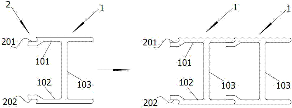
[0046] figure 1 A cross-sectional view of the anti-misalignment I-beam provided by Embodiment 1 of the present invention. Such as figure 1 As shown, the locking slot 2 includes a first locking slot 201 and a second locking slot 202 . When the profile body 1 is cut transversely, the first locking groove 201 is located on the upper surface of the left end of the upper wing 101 , and the second locking groove 202 is located on the lower surface of the left end of the lower wing 102 . In this embodiment, the first slot 201 and the second slot 202 with different positions, when a plurality of anti-slip I-beams are spliced in parallel, any anti-slip I-beam can prevent adjacent anti-slip I-beams The beam moves up and down. Since the first slot 201 and the second slot 202 are arranged on the same side of the I-beam, the I-beam presents a horizontally symmetrical structure, and the center of gravity is relatively stable for easy transportation.
Embodiment 2
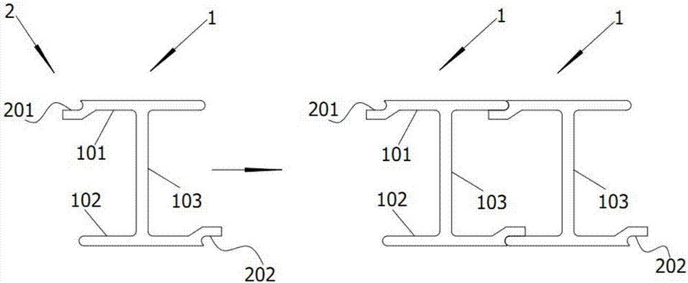
[0048] figure 2 A cross-sectional view of the anti-misalignment I-beam provided by Embodiment 2 of the present invention. Such as figure 2 As shown, the locking slot 2 includes a first locking slot 201 and a second locking slot 202 . When the profile body 1 is cut transversely, the first locking groove 201 is located on the upper surface of the left end of the upper wing 101 , and the second locking groove 202 is located on the lower surface of the right end of the lower wing 102 . In this embodiment, similarly, the first card slot 201 and the second card slot 202 with different positions, when multiple anti-stagger I-beams are spliced in parallel, any one anti-stagger I-beam can prevent adjacent anti-stagger I-beams Stagger the I-beam up and down. However, since the first clamping slot 201 and the second clamping slot 202 are arranged on different sides of the I-beam, a single I-beam is more evenly subjected to displacement force.
Embodiment 3
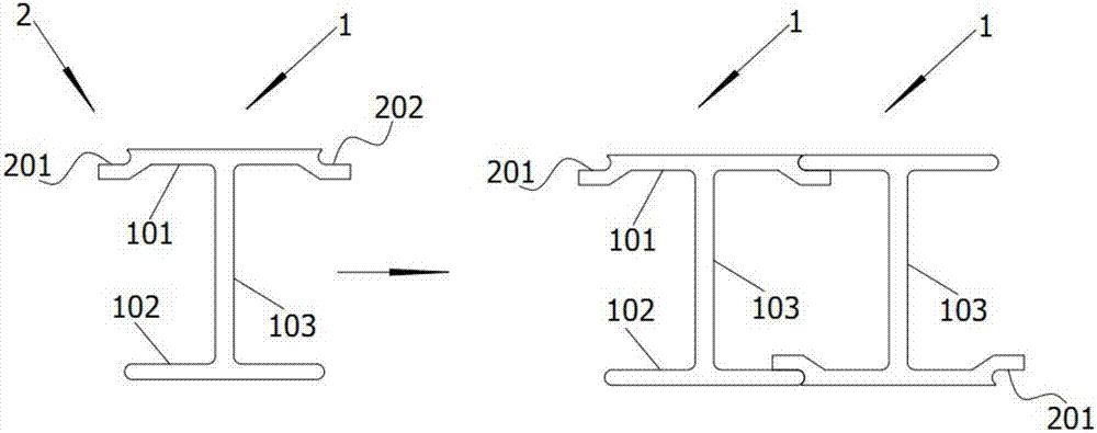
[0050] image 3 A sectional view of the anti-misalignment I-beam provided by Embodiment 3 of the present invention. Such as image 3 As shown, the locking slot 2 includes a first locking slot 201 and a second locking slot 202 . When the profile body 1 is cut transversely, the first locking groove 201 is located on the upper surface of the left end of the upper wing 101 , and the second locking groove 202 is located on the upper surface of the right end of the upper wing 101 . In this embodiment, similarly, the first card slot 201 and the second card slot 202 with different positions, when multiple anti-stagger I-beams are spliced in parallel, any one anti-stagger I-beam can prevent adjacent anti-stagger I-beams Stagger the I-beam up and down. Since the first draw-in slot 201 and the second draw-in slot 202 are both arranged on the upper wing 101 of the I-beam, the structure of the lower wing 102 remains flat, which is convenient for transportation and storage.
PUM
 Abstract
Description
Claims
Application Information
 - R&D
- Intellectual Property
- Life Sciences
- Materials
- Tech Scout
- Unparalleled Data Quality
- Higher Quality Content
- 60% Fewer Hallucinations
Browse by: Latest US Patents, China's latest patents, Technical Efficacy Thesaurus, Application Domain, Technology Topic, Popular Technical Reports.
© 2025 PatSnap. All rights reserved.Legal|Privacy policy|Modern Slavery Act Transparency Statement|Sitemap|About US| Contact US: help@patsnap.com