
Multi-stage hydraulic pressurizer based on mechanical device

A mechanical device and hydraulic pressurization technology, applied in the direction of drill pipe, casing, drill pipe, etc., can solve the problems of easily damaged nozzles, difficult WOB transmission, easy to get stuck, etc., to achieve long service life and improve drilling stability. , the effect of reliable work

Active Publication Date: 2019-04-26
山东王晁煤电集团新能发电有限公司
View PDF4 Cites 0 Cited by
  • Summary
  • Abstract
  • Description
  • Claims
  • Application Information

AI Technical Summary

Problems solved by technology

[0005] In order to solve the problems in the oil and gas production process described in the background technology, such as drill jumping, underpinning pressure, and difficult transmission of WOB, as well as the existing hydraulic pressurizer nozzles, which are easily damaged and easily stuck, etc., to achieve effective transmission of WOB and improve drilling efficiency , the present invention provides a multi-stage hydraulic pressurizer based on a mechanical device

Method used


Image

  • Multi-stage hydraulic pressurizer based on mechanical device
  • Multi-stage hydraulic pressurizer based on mechanical device
  • Multi-stage hydraulic pressurizer based on mechanical device

Examples


Embodiment Construction

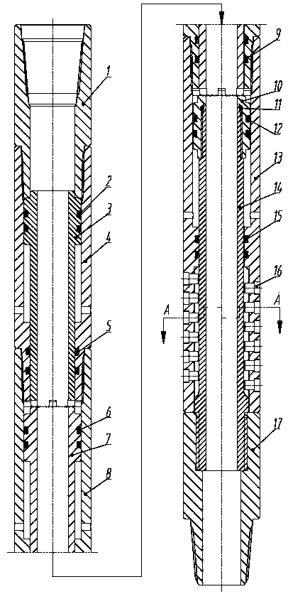
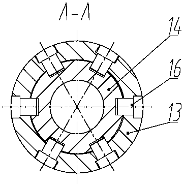
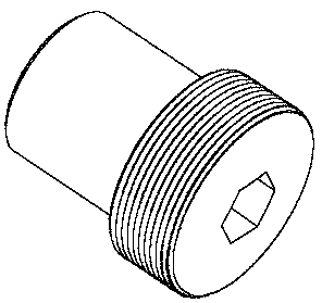
[0014] Below in conjunction with figure, the present invention will be further described:

[0015] According to the drawings, the multi-stage hydraulic pressurizer based on mechanical device is composed of an upper joint 1, a seal ring a2, a three-stage piston 3, a three-stage piston cylinder 4, a seal ring b5, a seal ring c6, a two-stage Composed of piston 7, secondary piston cylinder 8, sealing ring d9, main piston 10, sealing ring e11, sealing ring f12, main piston cylinder 13, main piston rod 14, sealing ring g15, roller 16 and lower joint 17, its characteristics That is: the three-stage piston cylinder 4 is connected to the lower end of the upper joint through threads, and the seal ring a2, the three-stage piston 3, and the seal ring b5 are sequentially installed inside the three-stage piston cylinder 4; then the seal ring c6, the two-stage piston 7 , sealing ring d9 is installed in the secondary piston cylinder 8; the main piston cylinder 13 is located between the second...


PUM


Abstract

The invention relates to a three-stage one-stroke hydraulic pressurizer applied to drilling of conventional wells, slim holes and micro-holes. The technical scheme of the three-stage one-stroke hydraulic pressurizer is that an upper joint, different stages of piston cylinders and a lower joint are connected sequentially through threads; the lower end of the upper joint of the hydraulic pressurizer is connected with a third-stage piston cylinder through threads; the third-stage piston cylinder and a second-stage piston cylinder are connected with a main piston cylinder; a third-stage piston, a second-stage piston and a main piston are mounted in the corresponding cylinder bodies respectively; the main piston cylinder and a main piston rod are flexibly connected through a roller mounted on the cylinder body and a keyway formed in the piston rod; the upper end of the main piston rod is connected with the main piston through threads, and the lower end of the main piston rod is fixed on the lower joint through threads. With adoption of the hydraulic pressurizer, mud power is converted into axial thrust, so that constant bit pressure is applied to a drill bit, the bit pressure transfer efficiency can be increased, the problems of bit jumping, backing pressure and the like are solved effectively, the service life of the drill bit is prolonged, fatigue failures of a drilling tool are reduced, and drilling efficiency is increased.

Description

technical field [0001] The invention relates to a multi-stage hydraulic pressurizer based on a mechanical device used for drilling conventional boreholes, slim boreholes and tiny boreholes, and can be used for downhole operations in the process of oil and natural gas exploitation. Background technique [0002] In oil and gas drilling operations, the way to apply WOB in conventional wellbore drilling is to rely on the gravity of the drill bit to apply WOB to the drill bit, and then realize the rock-breaking drilling of the drill bit. This traditional rigid pressure method has many unavoidable problems. The disadvantages of drilling, such as uneven feeding, jumping drill, bending of drilling tools, back pressure, etc., these disadvantages not only affect the ROP, but also cause rapid wear of the drill string and drill bit, seriously affecting the life of the drill bit and drilling tool. [0003] However, slimhole and micro-hole drilling is an emerging high-efficiency, low-cost...

Claims


Application Information

Patent Timeline
Patent Type & Authority Patents(China)
IPC IPC(8): E21B19/086
CPCE21B19/086
Inventor 田家林李居瑞杨琳朱志李居良张堂佳林晓月杨毅
Owner 山东王晁煤电集团新能发电有限公司
Learn More