Supercharge Your Innovation With Domain-Expert AI Agents!

A linear guide rail at the end of a robot

A linear guide, robot technology, applied in manipulators, program-controlled manipulators, manufacturing tools, etc., can solve the problems of increasing the use, maintenance and repair costs of robots, assembly difficulties, and high requirements for machining accuracy, so as to reduce production and maintenance costs and avoid partial wear and tear. Serious effects with low requirements on machining accuracy

Active Publication Date: 2020-08-04
QINGDAO FENGGUANG PRECISION MACHINERY
View PDF6 Cites 0 Cited by
  • Summary
  • Abstract
  • Description
  • Claims
  • Application Information

AI Technical Summary

Problems solved by technology

The rows of steel balls in the chute of the slider and the track can neither be too tight nor too loose, but must be precisely matched at the micron level; the processing accuracy is high, the assembly is difficult, and it is easy to damage
[0004] In order to prevent the steel balls from being misaligned and squeezed each other in the chute, a cage is usually added to the steel balls, and in order to prevent the steel balls from falling off, a baffle is also provided. One-position assembly is extremely inconvenient; it also makes it easy to damage and difficult to maintain, and also increases the cost of robot maintenance and repair

Method used


Image

  • A linear guide rail at the end of a robot

Examples


Embodiment Construction

[0020] In the following detailed description, numerous specific details are set forth in order to provide a thorough understanding of the present invention. However, it will be understood by those skilled in the art that the present invention may be practiced without these specific details. In other instances, well-known methods, procedures, components and circuits have not been described in detail so as not to obscure the present invention.

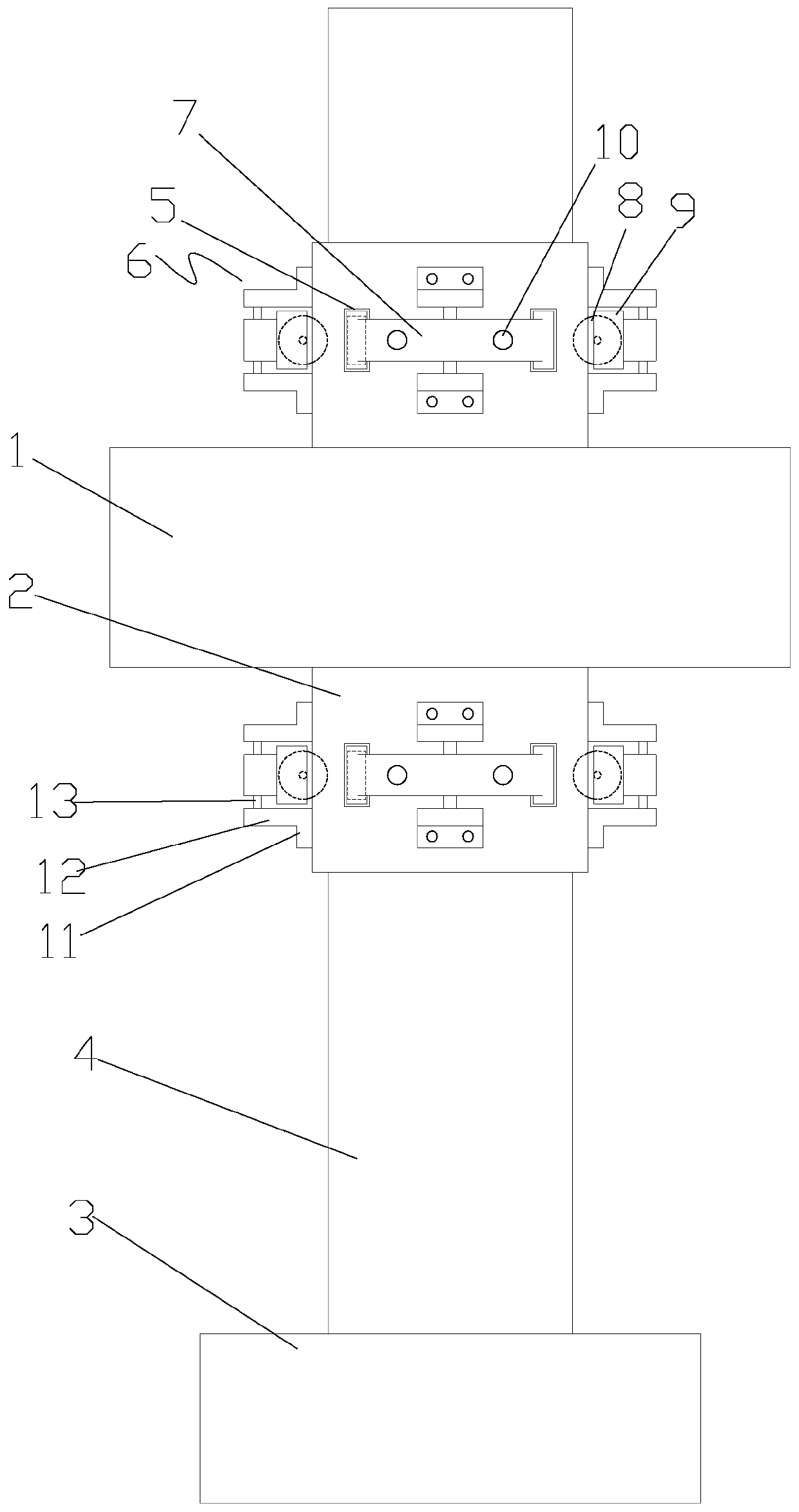
[0021] Such as figure 1 As shown, according to the embodiment of the present invention, the linear guide rail at the end of the robot includes a slider 2 connected to the end 1 of the robot and a track 4 connected to the frame 3 of the robot. The track 4 is a rectangular column, and the slider 2 is slidingly sleeved on the rectangular column. In addition, each side of the slider 2 is provided with two bearing holes 5 along the width direction, the slider 2 is fixedly provided with a mounting seat 6, and a connecting frame 7 is swingably...


PUM


Abstract

The invention relates to a robot tail end linear guide rail. The robot tail end linear guide rail comprises a sliding block (2) connected with a robot tail end (1) and a track (4) connected with a robot rack (3). The track (4) is a rectangular column. The sliding block (2) is arranged outside the rectangular column in sliding and sleeving modes. Each side face of the sliding block (2) is provided with two bearing holes (5) in the width direction. The sliding block (2) is fixedly provided with a mounting base (6). A connecting frame (7) is arranged on the mounting base (6) in a swinging mode. Bearings (8) are arranged at the two ends of the connecting frame (7) and are located in the corresponding bearing holes (5). The bearings (8) and the track (4) are in rolling fit in the sliding direction of the sliding block (2). The robot tail end linear guide rail is simple in structure, low in processing accuracy requirement, easy to assemble, and capable of achieving automatic balance and effectively prolonging the service life.

Description

technical field [0001] The invention relates to parts of a robot, in particular to a linear guide rail at the end of a robot. Background technique [0002] With the development and maturity of robot technology, there are more and more places where the end of the robot (manipulator and other actuators) needs to use linear motion, such as linear handling of materials, linear extension of robots and other common applications. The linear movement of the end of the robot is usually realized by a linear guide. [0003] The existing linear guide rail at the end of the robot includes a slider connected to the end, the slider cooperates with the track through several rows of steel balls, and the track is installed on the frame of the robot. The linear sliding between the slider and the track is realized by rolling several rows of steel balls in the chute of the slider and the track, and then the linear motion of the end of the robot is realized. The rows of steel balls in the chute...

Claims


Application Information

Patent Timeline
Patent Type & Authority Patents(China)
IPC IPC(8): B25J9/10
CPCB25J9/109
Inventor 李军
Owner QINGDAO FENGGUANG PRECISION MACHINERY
Features
  • R&D
  • Intellectual Property
  • Life Sciences
  • Materials
  • Tech Scout
  • Unparalleled Data Quality
  • Higher Quality Content
  • 60% Fewer Hallucinations
Learn More