Eureka AIR delivers breakthrough ideas for toughest innovation challenges, trusted by R&D personnel around the world.

Turbocharger with variable axial section

A turbocharger, axial technology, used in machines/engines, internal combustion piston engines, mechanical equipment, etc., can solve the problem that the nozzle ring blades cannot adapt to the high temperature exhaust of the engine, the reliability of the variable nozzle ring is poor, and the manufacturing accuracy is high. problems, to achieve the effect of fast and sensitive adjustment process, improved driving safety performance, and low material requirements

Inactive Publication Date: 2017-08-29
TONGJI UNIV
View PDF6 Cites 3 Cited by
  • Summary
  • Abstract
  • Description
  • Claims
  • Application Information

AI Technical Summary

Problems solved by technology

However, the adjustment method is basically stage adjustment, that is, there are only two or limited working opening positions, it is difficult to maintain high efficiency in the entire operating condition, and the reliability of the variable nozzle ring is poor, which requires high manufacturing accuracy. High, and because the nozzle ring blades of ordinary materials cannot adapt to the high-temperature exhaust of the engine, there are still disadvantages such as complex structure and high manufacturing cost

Method used


Image

  • Turbocharger with variable axial section
  • Turbocharger with variable axial section
  • Turbocharger with variable axial section

Examples


Embodiment 1

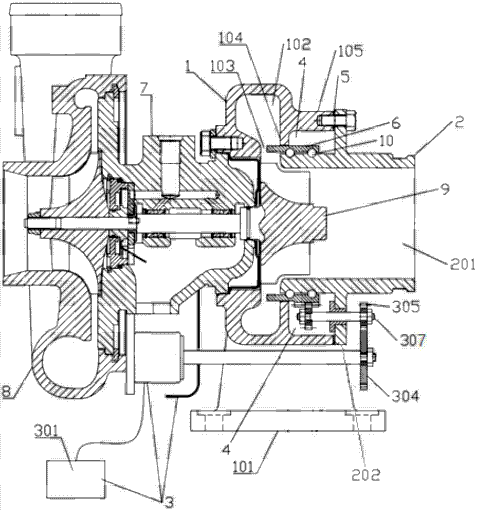
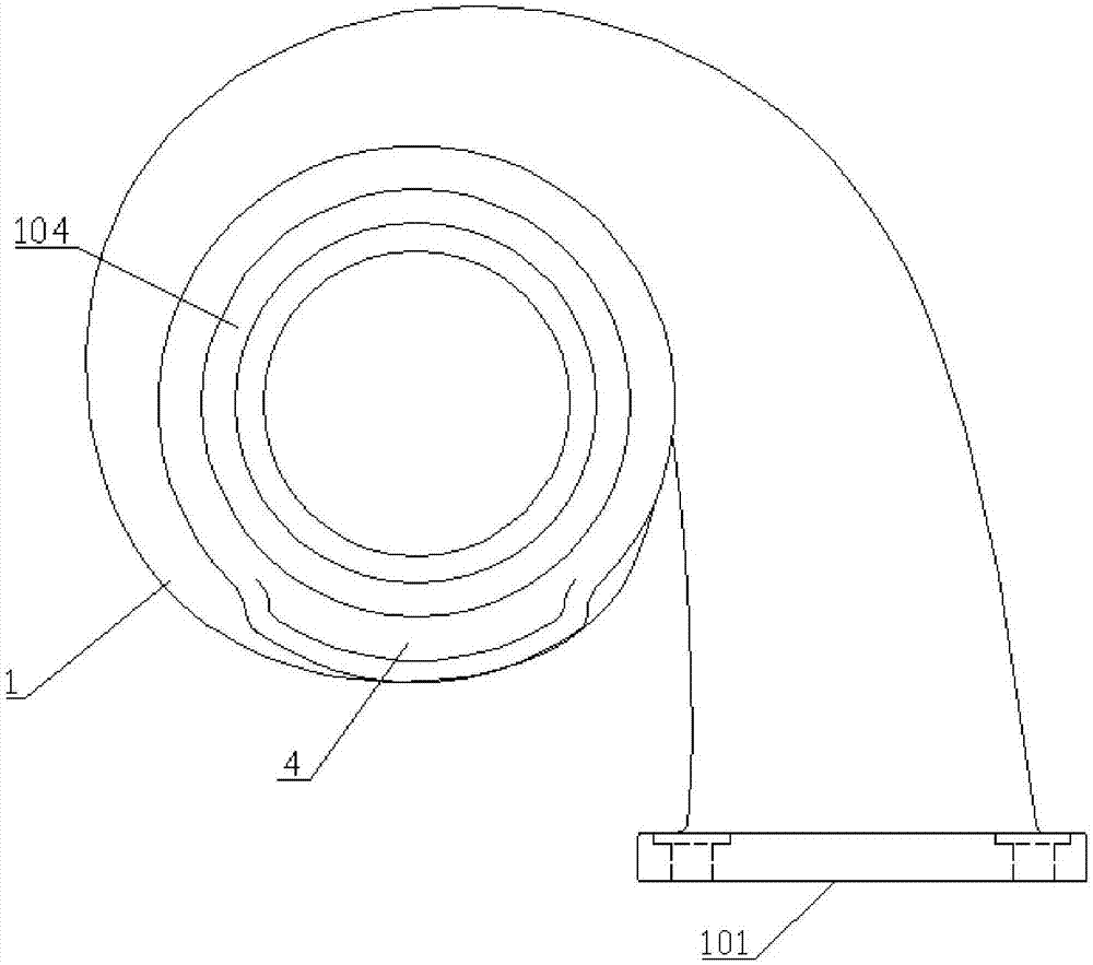
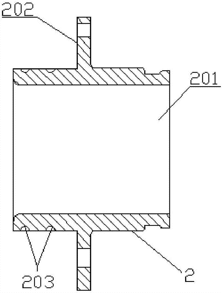
[0039] like figure 1 Shown is an axially variable cross-section turbocharger, which includes a compressor 8 , an intermediate body 7 , a turbine casing 1 and an exhaust casing 2 connected in sequence. like figure 2 As shown, the turbine casing 1 is provided with an exhaust gas inlet 101 , and inside is provided with a turbine 9 and a vortex channel 102 communicating with the exhaust gas inlet 101 and the turbine 9 respectively. One end of the exhaust casing 2 is provided with an exhaust outlet 201, and a cavity 4 and a movement control ring 6 are arranged between the inner side of the turbine casing 1 and the outer side of the exhaust casing 2, and one end of the movement control ring 6 is located Between the pipe flow channel 102 and the turbine 9, the other end is located in the cavity 4, and the turbocharger also includes an electric control actuator 3 connected to the moving control ring 6, and the electric control actuator 3 drives the moving control ring 6 along the T...

Embodiment 2

[0046] In this embodiment, the included angle between the second rolling chute 601 and the central axis of the mobile control ring 6 is 15°, and the rest are the same as in Embodiment 1.

Embodiment 3

[0048] In this embodiment, the included angle between the second rolling chute 601 and the central axis of the mobile control ring 6 is 75°, and the rest are the same as in Embodiment 1.


PUM


Abstract

The invention relates to a turbocharger with a variable axial section. The turbocharger comprises a compressor, an intermediate, a turbine shell and an exhaust shell which are connected in sequence; the turbine shell is provided with a waste gas inlet and is internally provided with a turbine and a vortex tube flow pass communicated with the waste gas inlet and the turbine respectively, one end of the exhaust shell is provided with an exhaust outlet, a cavity body and a moving control ring are arranged between the inner side of the turbine shell and the outer side of the exhaust shell, one end of the moving control ring is located between the vortex tube flow pass and the turbine while the other end is located in the cavity body, and the turbocharger further comprises an electronic control execution mechanism in transmission connection with the moving control ring. Compared with prior art, the axial variable section is realized by peripheral rotation and axial movement of the moving control ring, further an effective air inlet area of the turbine can be adjusted according to air inlet needs of an engine, the structure is simple, the manufacturing cost is low, the control is easy and safety and reliability are realized.

Description

technical field [0001] The invention belongs to the technical field of engine turbocharging, and relates to a turbocharger with variable axial section. Background technique [0002] A turbocharger is a device that increases the amount of intake air by compressing air. It uses the inertial momentum of the exhaust gas discharged from the engine to drive the turbine in the turbine chamber, and the turbine drives the coaxial compressor impeller. The compressor impeller is pressed by The air from the air filter pipe is pressurized into the cylinder. When the engine speed increases, the exhaust gas discharge speed and the turbine speed also increase synchronously, and the compressor impeller compresses more air into the cylinder, and the pressure and density of the air increase to burn more fuel, which increases the fuel volume and The speed of the engine increases the output power of the engine. Since the vehicle engine needs to adapt to different road conditions and loads, its...

Claims


Application Information

Patent Timeline
IPC IPC(8): F02B37/22
CPCF02B37/22Y02T10/12
Inventor 范厚传倪计民
Owner TONGJI UNIV
Why Eureka
Eureka Blog
Learn More