
Vortex compressor for vehicle

A scroll compressor and compression mechanism technology, applied in the field of compressors, can solve the problems of redundant lead wire length, leakage, and lead wires touching surrounding metal parts, etc., to achieve improved insulation and reliability, and sufficient operation Good effect of space and insulation

Active Publication Date: 2017-08-29
SHANGHAI HIGHLY NEW ENERGY TECH CO LTD
View PDF8 Cites 5 Cited by
  • Summary
  • Abstract
  • Description
  • Claims
  • Application Information

AI Technical Summary

Problems solved by technology

If the terminal is installed on the casing cover, after the assembly of the lead wire and the terminal is completed and the cover and the shell form a closed cavity, the lead wire will inevitably have a redundant length, otherwise the compressor cavity cannot be closed before the cavity is closed. Assembling lead wires and terminal posts
Due to the vibration when the compressor is running, the extended lead wires may touch the surrounding metal parts. Once the insulation protection layer of the lead wires is damaged and the exposed wires touch the metal parts, electric leakage will occur, which will affect the insulation performance of the whole machine. Reliability is bad
If the terminal is also installed on the shell, since the assembly of the lead wire and the terminal needs to occupy a certain amount of operating space, if the space of the shell is tight, the assembly and inspection operations are inconvenient, and if the shell is reserved for operating space, it is not conducive to Compressor downsizing
Therefore, when connecting the lead wires and the terminals, the structure of interference fitting the motor stator inside the housing will always have its disadvantages
[0004] 2) The terminal posts of most existing compressors are installed from the outside of the compressor
If the liquid refrigerant soaks into the connection between the terminal post and the motor lead wire, the insulation of the compressor will be greatly reduced

Method used


Image

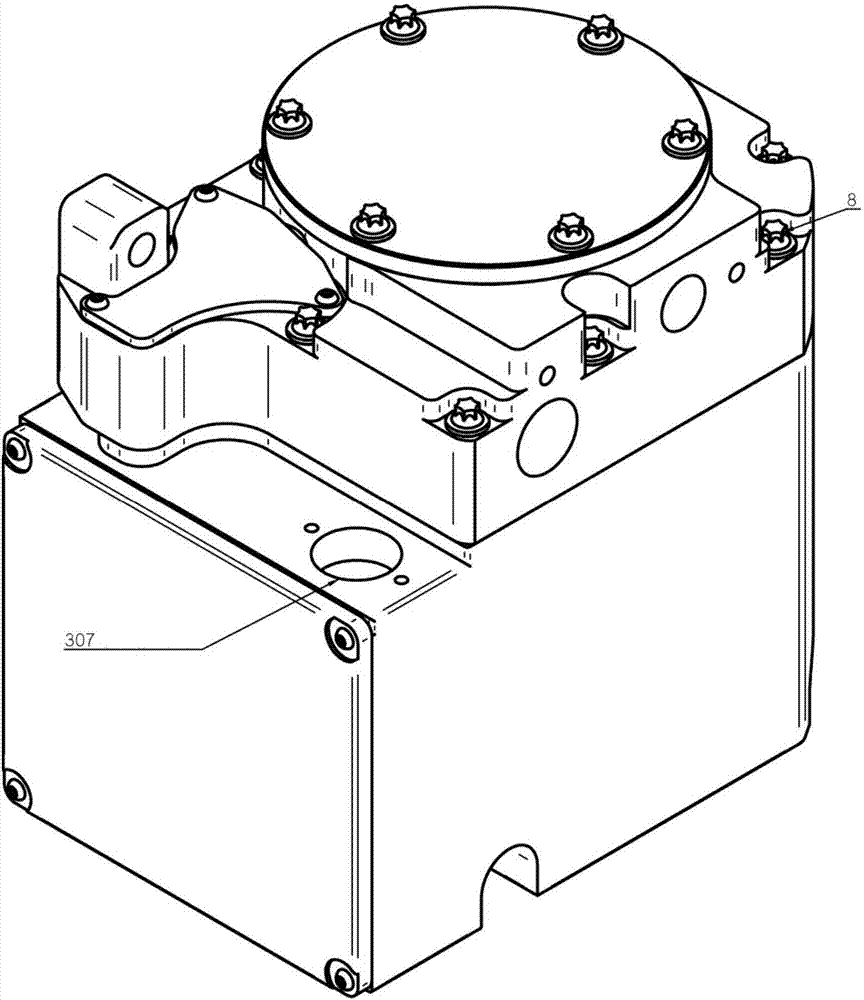
  • Vortex compressor for vehicle
  • Vortex compressor for vehicle
  • Vortex compressor for vehicle

Examples


Embodiment Construction

[0036] Example embodiments will now be described more fully with reference to the accompanying drawings. Example embodiments may, however, be embodied in many forms and should not be construed as limited to the embodiments set forth herein; rather, these embodiments are provided so that this disclosure will be thorough and complete, and will fully convey the concept of example embodiments to those skilled in the art. The same reference numerals denote the same or similar structures in the drawings, and thus their repeated descriptions will be omitted.

[0037] In order to improve the defects of the prior art, the present invention provides a compressor, preferably a scroll compressor for vehicles. Various embodiments are described below by taking a vertical structure, that is, a compressor in which the axis of the shaft transmission mechanism and the scroll pump body is arranged vertically, but the present invention is not limited thereto. The compressor provided by the pres...


PUM


Abstract

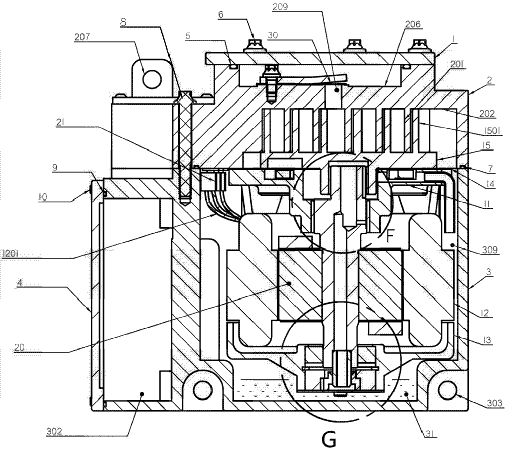
The invention provides a vortex compressor for a vehicle. The vortex compressor comprises a shell which is provided with a first opening to form an accommodating space, a compression mechanism, a motor mechanism which comprises a motor rotor and a motor stator, an upper bracket, and a lower bracket which is fixedly connected with the upper bracket through the motor stator, wherein the motor stator is connected to a binding post through a motor lead-out wire; the binding post is located between the inner wall of the shell and the outer wall of the motor stator and is far away from the bottom wall of the shell; the motor stator is directly or indirectly mounted on the same component together with the wiring post; a distance between an outgoing line of the motor lead-out wire and the binding post is fixed; furthermore, a connection and assembling process is completed before the same component and the shell form a closed cavity. The vortex compressor for the vehicle is favorable for assembling of the binding post.

Description

technical field [0001] The invention relates to the field of compressors, in particular to an electric compressor for vehicles. Background technique [0002] Existing compressors have the following characteristics and disadvantages when connecting the motor lead wires from the motor stator to the terminal: [0003] 1) Most of the motor stators are interference-fitted inside the housing, and then the motor lead wires are connected to the terminals installed on the housing or the housing cover. This connection process needs to be completed before the shell cover and the shell form a closed cavity. If the terminal is installed on the casing cover, after the assembly of the lead wire and the terminal is completed and the cover and the shell form a closed cavity, the lead wire will inevitably have a redundant length, otherwise the compressor cavity cannot be closed before the cavity is closed. Carry out the assembly of lead wires and terminal posts. Due to the vibration when t...

Claims


Application Information

Patent Timeline
Patent Type & Authority Applications(China)
IPC IPC(8): F04C23/02B60H1/32
CPCF04C23/02B60H1/3223F04C2240/803F04C2230/60F04C2240/40F04C18/0215F04C29/0085
Inventor 宋雪峰王玉强
Owner SHANGHAI HIGHLY NEW ENERGY TECH CO LTD
Learn More