UAV dynamic path planning method suitable for high-speed environment

A dynamic path and path planning technology, applied in non-electric variable control, vehicle position/route/altitude control, instruments, etc., can solve problems such as long stabilization time, complex system design, changing movement direction, etc., to reduce collisions. Risk, simplify system complexity, reduce the effect of closed loop

Inactive Publication Date: 2017-08-29
南通海嘉智能科技有限公司
View PDF4 Cites 17 Cited by
  • Summary
  • Abstract
  • Description
  • Claims
  • Application Information

AI Technical Summary

Problems solved by technology

However, path planning using the artificial potential field method is only suitable for low-speed environments. This is mainly due to three reasons: first, the bottleneck of hardware performance such as processors, sensors, and power systems; second, due to the theoretical defects of the artificial potential field method itself
Since the force of the potential field on the object in the potential field is only related to the position of the object and has nothing to do with the current state of motion of the object, the artificial potential field method cannot adjust the magnitude of the attractive and repulsive forces according to the motion state of the drone.
The third is that because the artificial potential field method uses the "desired position" as the output, two closed-loop loops, position control and attitude control, are required when designing the corresponding control system. The system design is complex, the stabilization time is long, and the expected position output cannot be obtained in time.
However, in a high-speed environment, since the acceleration provided by the power system has an upper limit, the control system also needs a certain stabilization time, so the UAV cannot change the direction of motion in a short time, and its actual motion path will have a large deviation from the ideal path.

Method used


Image

  • UAV dynamic path planning method suitable for high-speed environment
  • UAV dynamic path planning method suitable for high-speed environment
  • UAV dynamic path planning method suitable for high-speed environment

Examples


Embodiment Construction

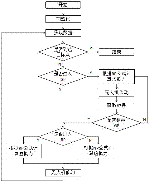
[0042] The specific steps of path planning are as follows:

[0043] (1) Set the target point coordinate c g And calculate the parameters, continue to step (2);

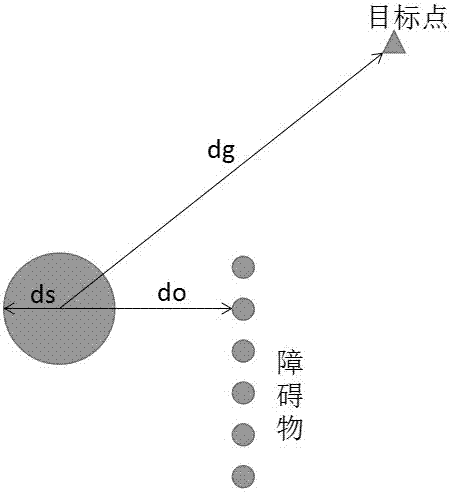
[0044] (2) Obtain the current position c and speed of the drone through the sensor Vector of drone pointing at obstacle Continue to step (3);

[0045] (3) To judge whether the target point is reached, the judgment conditions are:

[0046] Where ε v And ε d Is the set threshold, That is, the distance from the UAV to the target point; if the judgment condition is met, it is deemed to have reached the end point, and the path planning is ended. If it is not met, perform step (4);

[0047] (4) Judging whether to enter the stage of relief, the judgment conditions are:

[0048]

[0049] with Respectively represent the speed at time t and t-1, ε 1 Is the set threshold; if the judgment condition is met, it is deemed to have entered the stage of escape, and step (9) is executed; if it is not met, step (5) is executed;

[0050] (5) Ju...


PUM


Abstract

An UAV dynamic path planning method suitable for high-speed environment combines the theory of kinematic mechanics, establishes speed-dependent gravitational and repulsive functions, increases the virtual resistance, abandons the concept of "potential field", and directly calculates the resultant force born by the UAV through the virtual force function. The simulation experiments show that the method is effective and safe when the UAV is moving at high speed. The beneficial effect is that the method of the invention does not need to generate the motion path of the UAV, and only needs to calculate the expected resultant force of the UAV, not only reduces the complexity of the algorithm, but also substitutes the desired acceleration for the desired position as the input of the control system, so that one closed loop is omitted, the system complexity is lowered, the stabilizing time is greatly shortened, and the problem that the existing path planning method is not suitable for the high speed environment.

Description

Technical field [0001] The invention relates to the field of UAV path planning, in particular to a UAV dynamic path planning method suitable for high-speed environments. Background technique [0002] Path planning is one of the core technologies in the UAV field. The path planning methods currently used in the field of UAVs mainly include visualization method, fuzzy logic, neural network, genetic algorithm, ant colony algorithm, artificial potential field method and so on. Among the many path planning algorithms, the artificial potential field method has been widely studied and applied because of its many advantages, such as less information, easy implementation, simple expression, simple mathematical analysis, and small amount of calculation. The artificial potential field method (abbreviated as APF) also has obvious congenital defects, that is, the problems of "target unreachable" and "local minimum". At present, through the combination of artificial potential field method an...

Claims


Application Information

Patent Timeline
Patent Type & Authority Applications(China)
IPC IPC(8): G05D1/10
CPCG05D1/101
Inventor 郑国强李阳沈森王菲冀保峰马华红袁德颖尚佳庆王玉婷李济顺薛玉君
Owner 南通海嘉智能科技有限公司
Why Eureka
Try Eureka