Multilayer structure filtering antenna and microwave communication system

A multi-layer structure and filter antenna technology, applied to the structural form of radiation elements, antennas, slot antennas, etc., can solve the problems of reduced gain, low overall gain, difficult assembly, etc., to solve assembly problems, solve gain drop, high The effect of frequency selectivity

Active Publication Date: 2017-08-29
NANTONG RES INST FOR ADVANCED COMM TECH CO LTD
View PDF5 Cites 19 Cited by
  • Summary
  • Abstract
  • Description
  • Claims
  • Application Information

AI Technical Summary

Problems solved by technology

With the development of radio frequency systems, there have emerged some techniques for the co-design of filters and antennas, but there are non-radiating resonators, which reduce the overall efficiency of the antenna and thus reduce the gain.
In order to solve this problem, the antenna achieves filtering and radiation response through its own structure. The current design is mainly realized by stacking overhead metal patches. As the frequency increases, the overhead distance cannot be guaranteed, and assembly is difficult.
[0004] All in all, most of the existing filter antennas always have non-radiating resonators, which reduces the efficiency of the antenna, so the overall gain is low; and the filter antenna realized by stacking metal patches has the problem of difficult assembly when the frequency is high

Method used


Image

  • Multilayer structure filtering antenna and microwave communication system
  • Multilayer structure filtering antenna and microwave communication system
  • Multilayer structure filtering antenna and microwave communication system

Examples


Embodiment Construction

[0017] In order to facilitate the understanding of the present invention, the present invention will be described more fully below with reference to the associated drawings. Typical embodiments of the invention are shown in the drawings. However, the present invention can be embodied in many different forms and is not limited to the embodiments described herein. Rather, these embodiments are provided so that the disclosure of the present invention will be thorough and complete.

[0018] It should be noted that when an element is referred to as being “fixed” to another element, it can be directly on the other element or there can also be an intervening element. When an element is referred to as being "connected to" another element, it can be directly connected to the other element or intervening elements may also be present. The terms "vertical," "horizontal," "left," "right," and similar expressions are used herein for purposes of illustration only.

[0019] Unless otherwis...


PUM


Abstract

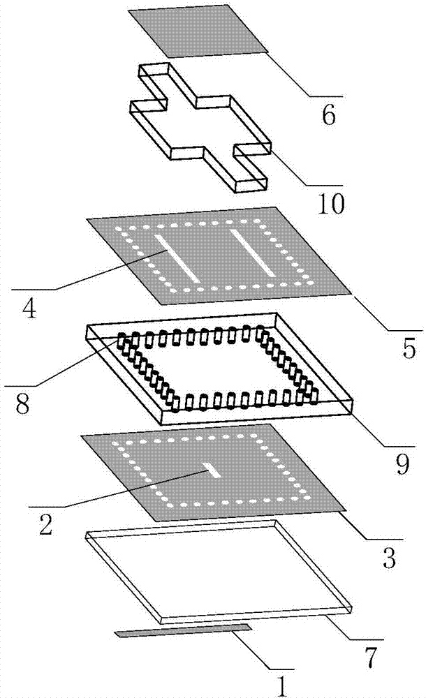
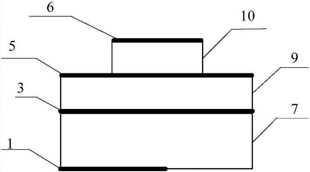
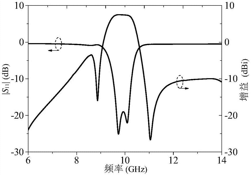
The present invention provides a multilayer structure filtering antenna and a microwave communication system. The multilayer structure filtering antenna comprises a first dielectric substrate, a second dielectric substrate and a third dielectric substrate which are overlapped from down to up; the lower surface of the first dielectric substrate is provided with a microstrip feeder; the lower surface and the supper surface of the second dielectric substrate are respectively provided with a first metal layer and a second metal layer, an entirety formed by the first metal, the second dielectric substrate and the second metal layer is provided with a plurality of metallization through holes in rectangular arrangement mode, the first metal layer, the second metal layer and a plurality of metallization through holes commonly form a rectangular resonant cavity, the first metal layer is provided with a coupling slot, and the second metal layer is provided with two opposite radiation slots; and the third dielectric substrate comprises a rectangular main body portion and two extension bodies, and the main body portion is provided with a radiation metal layer. The multilayer structure filtering antenna and the microwave communication system realize high-frequency selectivity, high gain and bandwidth improvement effects, solve the problem that the whole gain of the antenna id decreased caused by a non-radiation resonator, and realize assembling of a filtering antenna through the antenna itself.

Description

technical field [0001] The invention relates to the field of microwave communication, in particular to a multi-layer structure filter antenna and a microwave communication system. Background technique [0002] It is well known that filters provide frequency selectivity for microwave systems and therefore require resonators with high quality factors, while antennas require resonators with relatively low quality factors in order to provide radiation performance. Traditionally, filters and antennas are designed independently to achieve the best performance of each, however, from a system point of view, the overall size is too large and the efficiency is low. Therefore, combining the filtering function and the radiation function in a single device through structure sharing can improve the overall system efficiency. [0003] The most traditional way to implement a filter antenna is to directly cascade the antenna and filter together. With the development of radio frequency syst...

Claims


Application Information

Patent Timeline
Patent Type & Authority Applications(China)
IPC IPC(8): H01Q1/38H01Q13/10
CPCH01Q1/38H01Q13/106
Inventor 施金徐凯张威曹青华陈建新徐晨包志华
Owner NANTONG RES INST FOR ADVANCED COMM TECH CO LTD
Why Eureka
Try Eureka