Broadband receiver circuit with adjustable impedance matching frequency

A wideband receiver and impedance matching technology, applied in DC coupled DC amplifiers, differential amplifiers, and improved amplifiers to reduce noise effects, etc., can solve problems such as the inability to meet the design requirements of input impedance matching

Active Publication Date: 2020-07-07
NEWRADIO TECH CO LTD
View PDF5 Cites 9 Cited by
  • Summary
  • Abstract
  • Description
  • Claims
  • Application Information

AI Technical Summary

Problems solved by technology

The disadvantage of this technique is that it is only applicable to receivers with zero-IF structure, that is, the local oscillator clock frequency f LO and

Method used


Image

  • Broadband receiver circuit with adjustable impedance matching frequency
  • Broadband receiver circuit with adjustable impedance matching frequency
  • Broadband receiver circuit with adjustable impedance matching frequency

Examples


Embodiment Construction

[0023] The present invention proposes a broadband receiver circuit with adjustable impedance matching frequency, which will be described in detail below with reference to the drawings and embodiments.

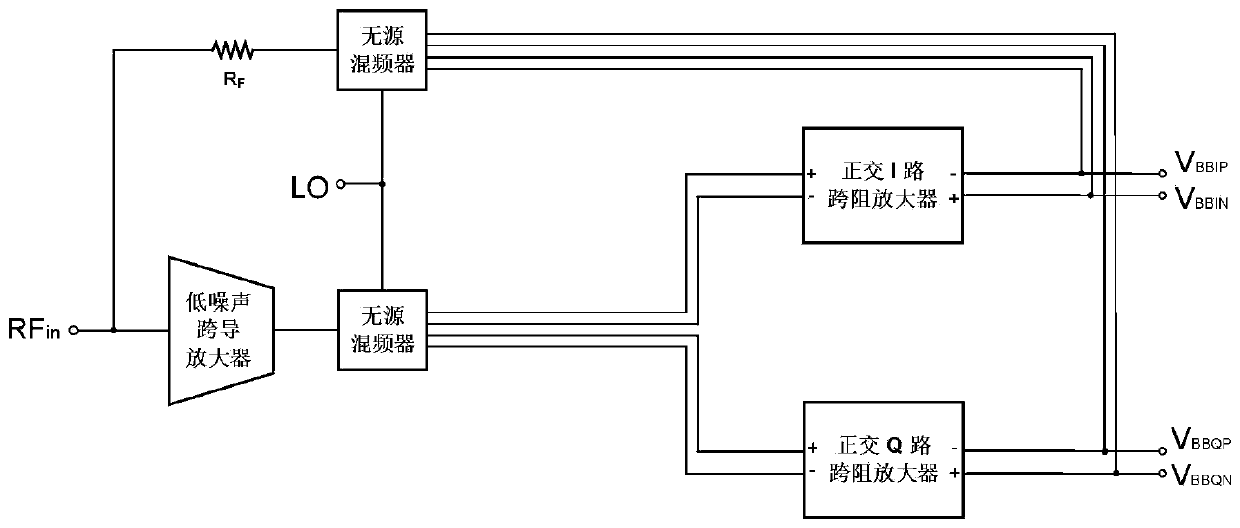
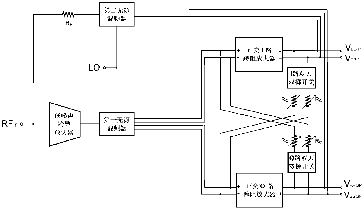
[0024] The present invention proposes a broadband receiver circuit with adjustable impedance matching frequency, the circuit structure diagram is as follows figure 2 shown, mainly includes a low noise transconductance amplifier, two passive mixers, a feedback resistor R F , quadrature transimpedance amplifiers I and Q with exactly the same circuit structure, two double-pole double-throw switches, and four variable resistors R C composition.

[0025] The circuit connection relationship of the broadband receiver circuit with adjustable impedance matching frequency proposed by the present invention is: the radio frequency input signal RF in Connected to the input of the low noise transconductance amplifier, while passing through the feedback resistor R F It is connected with t...


PUM


Abstract

The invention relates to a broadband receiver circuit with adjustable impedance matching frequency, which belongs to the field of radio frequency integrated circuits. The broadband receiver circuit comprises a low-noise transconductance amplifier, two passive frequency mixers, a quadrature trans-impedance amplifier I path, a quadrature trans-impedance amplifier Q path, a feedback resistor, two double-pole double-throw switches and four variable resistors, wherein a radio frequency input signal is connected with an input end of the low-noise transconductance amplifier and is connected with an input end of the second passive mixer through using the feedback resistor; an output end of the low-noise transconductance amplifier is connected with a signal input end of the first passive mixer; clock input ends of the two passive mixers are connected with four-phase non-overlapping clock signals; a signal output end of the first passive mixer is connected with a differential input end of the Ipath and a differential input end of the Q path; differential output signal ends of the I path and the Q path are connected with a four-phase input end of the second passive mixer; and the four variable resistors are bridged at input ends and output ends of the I path and the Q path through using the two double-pole double-throw switches. The broadband receiver circuit is suitable for zero-intermediate-frequency and low-intermediate-frequency receiver schemes.

Description

technical field [0001] The invention belongs to the technical field of receiver circuit design in radio frequency integrated circuit technology, in particular to a broadband receiver circuit with adjustable impedance matching frequency. Background technique [0002] The next generation of wireless communication requires that the front end of the radio frequency transceiver chip can cover a wide frequency band. For example, the fifth generation of mobile communication (5G) requires that the transceiver can support carrier frequencies from hundreds of MHz to 6GHz. The performance requirement of wideband adjustable carrier frequency poses a challenge to the design of RF receiver chips, especially for the front-end low-noise amplifier, which not only requires low noise figure and high dynamic range, but also requires the input matching circuit to cover the entire frequency band . [0003] In a traditional broadband receiver circuit, the function of input impedance matching is u...

Claims


Application Information

Patent Timeline
IPC IPC(8): H03F1/26H03F3/45
CPCH03F1/26H03F3/45Y02D30/70
Inventor 陈润陈振骐陈勇刚代伐
Owner NEWRADIO TECH CO LTD
Why Eureka
Try Eureka