Multi-band tunable microstrip band-pass filter

A filter and multi-band technology, applied in resonators, waveguide-type devices, electrical components, etc., can solve the problems of large volume, high system cost, single signal processing frequency band, etc. of multi-band systems, to simplify complexity and improve frequency Selective, fast-tuning effects

Inactive Publication Date: 2014-09-10
SHANGHAI UNIV
View PDF5 Cites 11 Cited by
  • Summary
  • Abstract
  • Description
  • Claims
  • Application Information

AI Technical Summary

Problems solved by technology

[0004] The purpose of the filter of the present invention is to provide a multi-band tunable filter for the traditional multi-band system with large volume and high system cost, and the filter bank composed of multiple single-band filters and a single signal processing frequency band. band pass filter

Method used


Image

  • Multi-band tunable microstrip band-pass filter
  • Multi-band tunable microstrip band-pass filter
  • Multi-band tunable microstrip band-pass filter

Examples


Embodiment 1

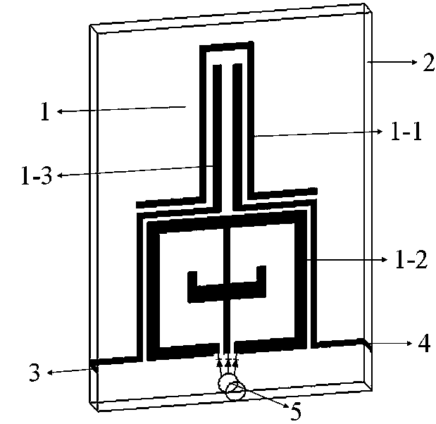
[0032] see figure 1 , the multi-band tunable microstrip bandpass filter includes a three-layer structure: the metal microstrip line on the front (1), the middle dielectric layer (2), and the input and output ports (3, 4) and the ground metal via ( 5), and the metal coating on the reverse side of the dielectric plate. The metal microstrip line is a resonator with a symmetrical structure composed of a half-wavelength uniform impedance line resonator (1-1) and an open-loop dual-mode resonator (1-2), so it can be analyzed by odd and even mode theory, The two resonators share the input and output coupling lines, and a varactor diode is loaded between the end of the open-loop dual-mode resonator and the ground metal through hole (5), forming a tuneable structure.

Embodiment 2

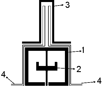
[0034] This embodiment is basically the same as Embodiment 1, the metal microstrip line on the front is as figure 2 , the special feature is: the open-loop dual-mode resonator is composed of an open-loop square-ring resonator (1) loaded with a Ψ-shaped open-circuit stub (2) in the middle, and its structure is symmetrical to generate resonance frequencies of two modes. The half-wavelength uniform impedance line (3) resonator adopts a bent structure, which reduces the area of ​​the filter and meets the requirement of miniaturization. The input-output coupling line (4) is fed through the gap coupling, and an additional finite-frequency transmission zero point is added when the applied voltage is low, thereby improving the attenuation characteristics of the filter. The dielectric plate layer is a dielectric constant The medium plate, the thickness of the medium plate h = 0.508mm.

Embodiment 3

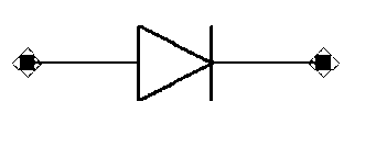
[0036] This embodiment is basically the same as Embodiment 2, in particular, a varactor diode ( image 3 ), load the varactor diode with reverse bias voltage through the DC bias circuit, change the resonant frequency of the odd and even modes to achieve the purpose of adjusting the center frequency and bandwidth of the band-pass filter.

[0037] Figure 4 It is a structural schematic diagram of the present embodiment. Through design, simulation and optimization, the specific dimensions of the multi-pass band adjustable band-pass filter are finally determined as follows:

[0038] L1=8.0mm, L2=7.75mm, L3=7.6mm, L4=6.1mm, L5=1.6mm, L6=0.8mm,

[0039] W1=3.3mm, W2=4.32mm, W3=3.75mm, W4=2.75mm, W5=4.0mm, W6=2.8mm,

[0040] D1=0.3mm, D2=0.25mm, D3=0.6mm, D4=0.3mm, D5=0.4mm, d=0.508mm,

[0041] r=0.4mm

[0042] Based on the above method, a three-band microstrip filter with a center frequency of 2.68GHz / 4.66GHz / 5.88GHz is designed, which is simulated and debugged by the electromag...


PUM


Abstract

The invention discloses a multi-band tunable microstrip band-pass filter which comprises a three-layer structure: a front metal microstrip line, a middle dielectric plate layer, input and output ports and an earthing metal through hole, and a metal coating at the back of a dielectric plate, wherein the metal microstrip line is a symmetric resonator consisting of a half-wavelength uniform impedance line resonator and an open-loop dual-mode resonator; the two resonators share input and output coupling lines; and a variable capacitance diode is loaded between the tail end of the open-loop dual-mode resonator and the earthing metal through hole to form a tunable structure. The filter is compact in structure, low in passband insertion loss, steep in passband edge and high in selectivity, and meets a development trend of filter miniaturization.

Description

technical field [0001] The invention relates to a multi-band tunable microstrip bandpass filter, which belongs to the field of wireless communication systems. While realizing three adjustable passbands, it has high out-of-band suppression and satisfies the characteristics of miniaturization. Background technique [0002] At present, the application frequency bands of communication systems are all concentrated in the low-frequency bands of radio frequency and microwave bands, which makes spectrum resources particularly crowded. In order to improve system capacity and avoid interference between the system and adjacent channels, it is very necessary to set up multiple communication frequency bands that can work simultaneously in the communication system. However, to realize dual-band or multi-band communication, each frequency band needs an independent RF front-end component, which makes the overall system larger in size and power consumption, and higher in cost. If the RF fro...

Claims


Application Information

Patent Timeline
Patent Type & Authority Applications(China)
IPC IPC(8): H01P1/203H01P7/08
Inventor 李国辉鉴浩王焕英李伟
Owner SHANGHAI UNIV
Why Eureka
Try Eureka