
Microstrip tri-band bandpass filter

A filter and microstrip technology, applied in waveguide devices, electrical components, circuits, etc., can solve problems such as difficult control of frequency and bandwidth, and achieve low insertion loss, high isolation between passbands, and small overall size.

Inactive Publication Date: 2014-10-29
UNIV OF ELECTRONICS SCI & TECH OF CHINA
View PDF7 Cites 12 Cited by
  • Summary
  • Abstract
  • Description
  • Claims
  • Application Information

AI Technical Summary

Problems solved by technology

The resonator of this filter works on three frequencies at the same time, resulting in three passbands, but the three frequencies are interrelated, and the frequency and bandwidth are difficult to control

Method used


Image

  • Microstrip tri-band bandpass filter
  • Microstrip tri-band bandpass filter
  • Microstrip tri-band bandpass filter

Examples


Embodiment Construction

[0020] The specific embodiments of the present invention will be further described below in conjunction with the accompanying drawings.

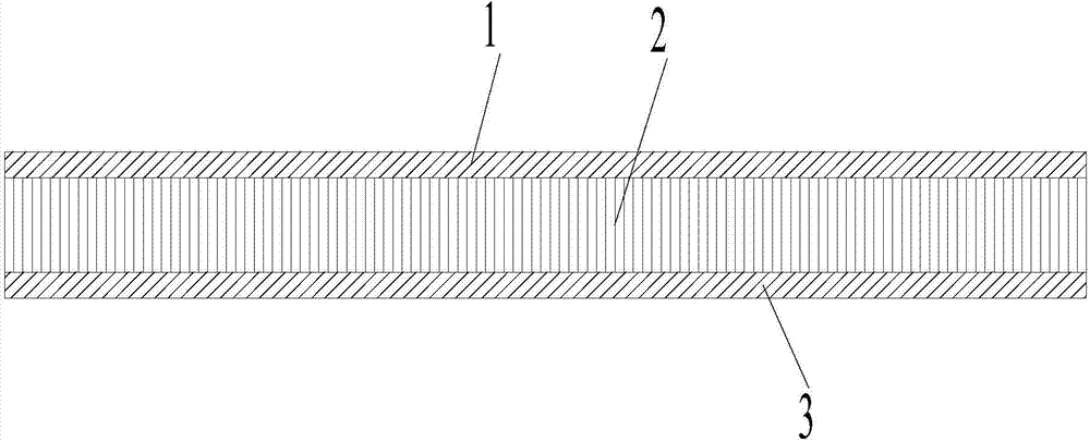
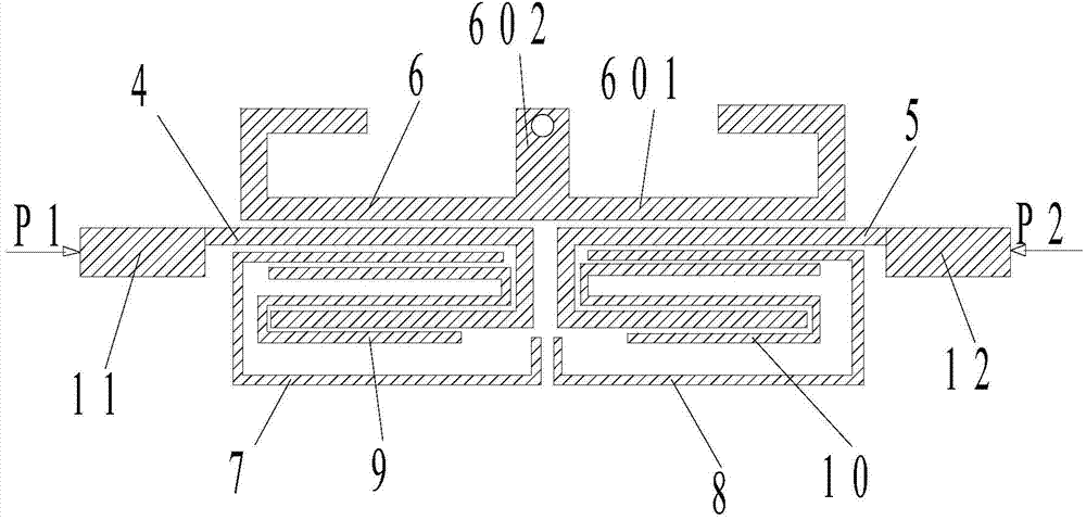
[0021] Such as figure 1 , 2 As shown, the microstrip three-pass bandpass filter includes an upper metal layer 1, a dielectric substrate 2, and a lower metal layer 3 that are sequentially stacked from top to bottom, and a circuit structure is printed on the upper metal layer 1 , the circuit structure includes a first resonator 4, a second resonator 5, a short-circuit stub loaded half-wavelength resonator 6, a first U-shaped half-wavelength resonator 7, a second U-shaped half-wavelength resonator 8, a first S Type half-wavelength resonator 9, the second S-type half-wavelength resonator 10, the first feeder 11 and the second feeder 12, the first feeder 11 is connected to the first resonator 4, the second feeder 12 is connected to the second resonator 5 connected, the first resonator 4 and the second resonator 5 are coupled through a gap; the ...


PUM


Abstract

The invention discloses a microstrip tri-band bandpass filter. The microstrip tri-band bandpass filter is small in integral size and independently controllable in bandpass characteristics. The microstrip tri-band bandpass filter comprises an upper metal layer, a medium substrate and a lower metal layer which are stacked sequentially from top to bottom. The upper metal layer is printed with a circuit structure, which is composed of a first resonator, a second resonator, a short circuit stub loading half-wavelength resonator, a first U-type half-wavelength resonator, a second U-type half-wavelength resonator, a first S-type half-wavelength resonator, a second S-type half-wavelength resonator, a first feeder and a second feeder. By means of the structure above, three independent filter units can be obtained, and the bandpass frequency and the bandwidth of every filter unit can be adjusted separately, and meanwhile, good frequency selectivity, high interband isolation, low insertion losses and wide attenuation band can be obtained; meanwhile, the microstrip tri-band bandpass filter is compact in structure, small in integral size and applicable to popularization and application in the technical field of microwave filters.

Description

technical field [0001] The invention relates to the technical field of microwave filters, in particular to a microstrip three-pass band-pass filter. Background technique [0002] At present, in the field of communication, efficient spectrum utilization has a higher demand for RF filters, and communication systems often require simultaneous work in multiple frequency bands. For example, many devices must support simultaneous access to three frequency bands at the same time. It is necessary to realize the miniaturization of the communication system, so it is necessary to realize the transmission of the three frequency band signals without attenuation as much as possible, and to attenuate the out-of-band signals to the maximum extent. The miniaturization of the communication system requires the corresponding three-pass band filter to be realized. [0003] The existing three-pass band filter mainly has the following ways to realize: [0004] The first is to use multiple filter...

Claims


Application Information

Patent Timeline
Patent Type & Authority Applications(China)
IPC IPC(8): H01P1/203
Inventor 钱江李道通刘剑刚吴琪贾勇沈炀黄聪
Owner UNIV OF ELECTRONICS SCI & TECH OF CHINA
Learn More