Power grid automatic voltage control method and system taking global optimum as target

A globally optimal, automatic voltage technology, applied in the direction of AC network voltage adjustment, reactive power compensation, etc., can solve the problem of not being the global optimal value, unable to achieve the global optimal value, and not having a control strategy, method or system, etc. To achieve the effect of reducing network loss

Active Publication Date: 2017-08-29
STATE GRID CORP OF CHINA +2
View PDF4 Cites 16 Cited by
  • Summary
  • Abstract
  • Description
  • Claims
  • Application Information

AI Technical Summary

Problems solved by technology

But there is a problem in both modes: that is, the global optimal value cannot be achieved
Although the result obtained in the three-level voltage control in the three-level control mode is the global optimal value, after the coordination of the second-level voltage control, the obtained result is only a feasible value of the regional central bus voltage with the same global optim

Method used


Image

  • Power grid automatic voltage control method and system taking global optimum as target
  • Power grid automatic voltage control method and system taking global optimum as target
  • Power grid automatic voltage control method and system taking global optimum as target

Examples


Embodiment Construction

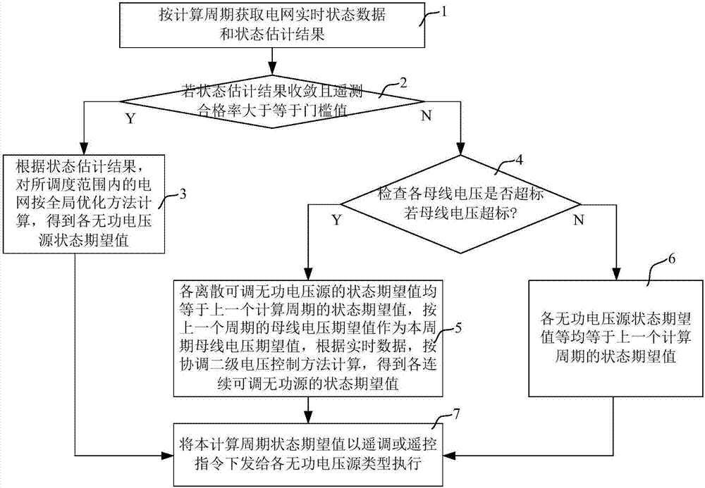
[0037] Such as figure 1 As shown, the implementation steps of the grid automatic voltage control method aiming at global optimization in this embodiment include:

[0038] 1) Acquire the real-time state data and state estimation results of the power grid according to the calculation cycle;

[0039] 2) If the state estimation result converges and the telemetry pass rate is greater than or equal to the threshold value, then skip to step 3), otherwise, skip to step 4);

[0040] 3) According to the state estimation results, the state expectation value of each reactive voltage source is calculated according to the global optimization method for the power grid within the dispatching range, and the state expectation value of each reactive voltage source includes the reactive output and output of the continuously adjustable reactive voltage source Grid-connected voltage, capacitor and reactor switching or switching status, transformer tap position; skip to step 7);

[0041] 4) Check ...


PUM


Abstract

The invention discloses a power grid automatic voltage control method and system taking global optimum as a target. The method comprises the steps of obtaining a real-time state evaluation result of the power grid according to calculation cycles, if the state evaluation result is converged and telemetering percent of pass is greater than or equal to a threshold value, calculating and obtaining a state expectation value of each reactive voltage source based on a global optimization method, or otherwise, if the bus voltage exceeds standard, assigning the state expectation value of each disperse and adjustable reactive voltage source with the value of the last calculation cycle separately, and calculating and obtaining the state expectation value of each continuous and adjustable reactive voltage source; if the bus voltage dose not exceed standard, assigning the state expectation value of each reactive voltage source with the value of the last calculation cycle separately; finally issuing and executing the corresponding state expectation values; and the system comprises respective units corresponding to the steps in the abovementioned method. According to the method and the system, power grid partitioning is not needed, the voltage requirement of each bus of the power grid can be satisfied while the global reactive power flow optimum is taken as the control target, so that the network loss can be further lowered, and the power grid global optimal economic operation can be realized.

Description

technical field [0001] The invention relates to an automatic voltage control technology of a power grid in a power system, in particular to an automatic voltage control method and system for a power grid aiming at global optimization. Background technique [0002] Automatic voltage control (Automatic Voltage Control, AVC) is the main system of modern power grid voltage and reactive power control. Control, improve the voltage quality of the power grid, reduce network loss, and ensure the safe, economical and high-quality operation of the power grid. [0003] The existing AVC system mainly has two modes: one is the three-level control mode, that is, the entire control system is divided into three levels: the third-level and the second-level voltage control are centralized control by the main station of the power grid regulation center at all levels, and the control time constant is generally It is at the minute level; the third-level voltage control calculates the expected va...

Claims


Application Information

Patent Timeline
IPC IPC(8): H02J3/16
CPCH02J3/16Y02E40/30
Inventor 吴晋波熊尚峰刘海峰陈宏李振文洪权李理郭思源蔡昱华欧阳帆朱维钧刘宇
Owner STATE GRID CORP OF CHINA
Why Eureka
Try Eureka