
MEMS microphone

A microphone and the same technology, applied in the field of acoustics, can solve the problems of affecting the vibration characteristics of the diaphragm, limited pressure relief capacity, and reducing the effective area of ​​the diaphragm, so as to avoid damage and improve the impact resistance.

Active Publication Date: 2017-08-29
WEIFANG GOERTEK MICROELECTRONICS CO LTD
View PDF8 Cites 6 Cited by
  • Summary
  • Abstract
  • Description
  • Claims
  • Application Information

AI Technical Summary

Problems solved by technology

But the structure of the pressure relief hole will reduce the effective area of ​​the diaphragm
The pressure relief valve structure set in the middle area of ​​the diaphragm will be limited by size, and its pressure relief capacity is limited; it will also directly affect the vibration characteristics of the diaphragm, especially the low-frequency characteristics of the diaphragm; the dynamic stability of the diaphragm is relatively poor

Method used


Image

  • MEMS microphone
  • MEMS microphone
  • MEMS microphone

Examples


Embodiment Construction

[0025] Various exemplary embodiments of the present invention will now be described in detail with reference to the accompanying drawings. It should be noted that the relative arrangements of components and steps, numerical expressions and numerical values ​​set forth in these embodiments do not limit the scope of the present invention unless specifically stated otherwise.

[0026] The following description of at least one exemplary embodiment is merely illustrative in nature and in no way taken as limiting the invention, its application or uses.

[0027] Techniques, methods and devices known to those of ordinary skill in the relevant art may not be discussed in detail, but where appropriate, such techniques, methods and devices should be considered part of the description.

[0028] In all examples shown and discussed herein, any specific values ​​should be construed as exemplary only, and not as limitations. Therefore, other instances of the exemplary embodiment may have dif...


PUM


Abstract

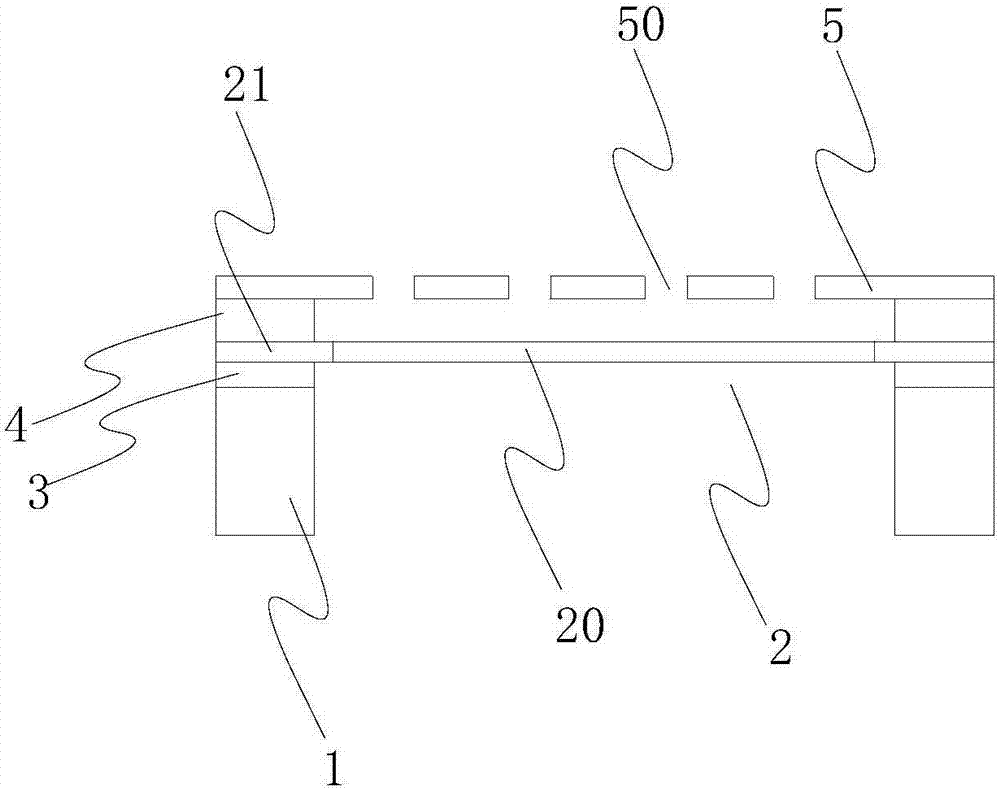
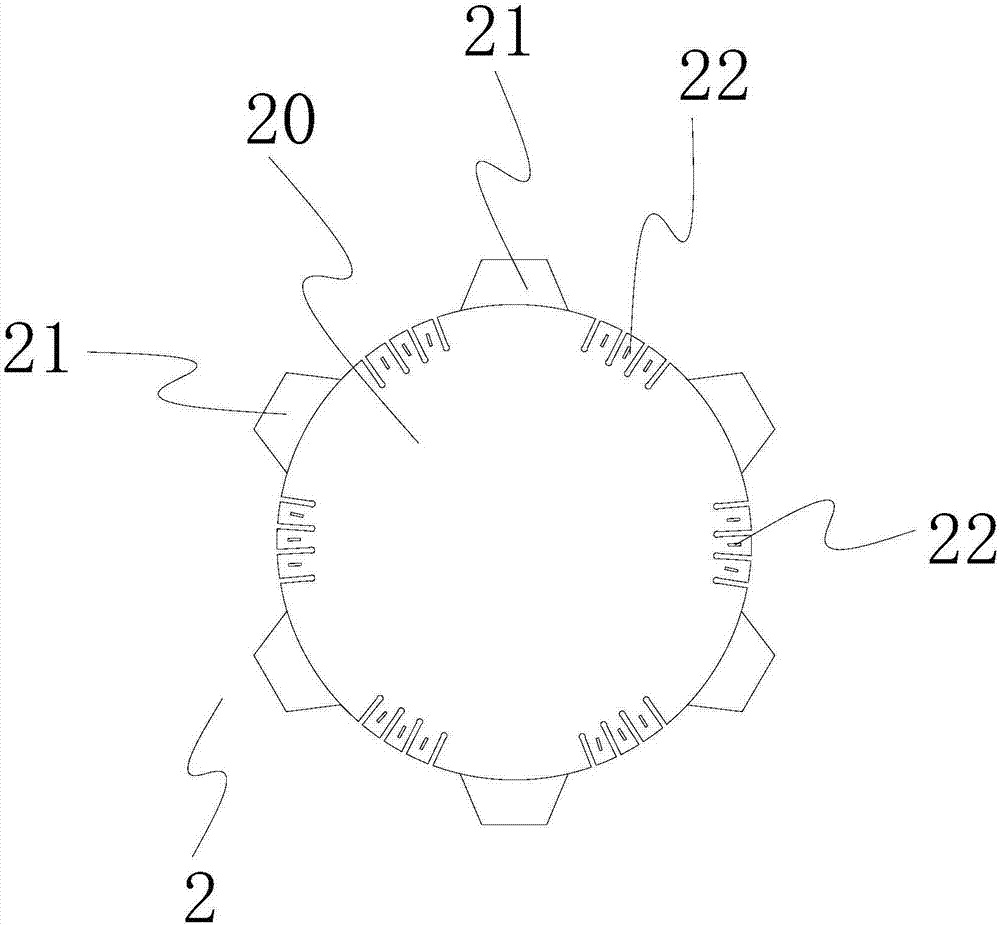
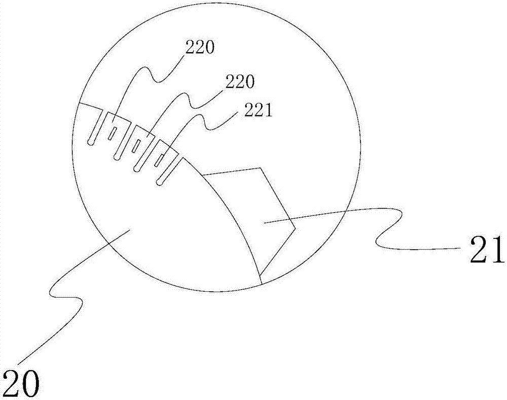
The invention discloses an MEMS microphone. The MEMS microphone comprises a substrate, and a vibrating diaphragm and a back pole located above the substrate, wherein a plurality of comb tooth parts are formed in edge positions of the vibrating diaphragm, and are distributed in the circumferential direction of the vibrating diaphragm at intervals; a part between every two adjacent comb tooth parts on the vibrating diaphragm is connected onto the substrate through an insulation layer; and the comb tooth parts on the vibrating diaphragm are at least partially superposed with the substrate, and a gap is formed between the comb tooth parts and the substrate and configured to be an air stream circulation channel for passage of air streams. The MEME microphone provided by the invention has the advantages that better anti-impact capability is achieved, and dust entry can be further avoided.

Description

technical field [0001] The present invention relates to the field of acoustics, more specifically, to a MEMS microphone. Background technique [0002] MEMS sensing components have been widely used in consumer electronics products. How to speed up the product production process is the focus of component suppliers. For example, the dust generated during the production and assembly of mobile phones is directly cleaned by air guns. The lowest cost option. Therefore, for MEMS sensors, it is necessary to propose a large-pressure or atmospheric-pressure anti-blow improvement plan to avoid rupture and failure of the microphone due to air gun cleaning during the assembly process. [0003] The current improvement solution is to provide a pressure relief hole or a pressure relief valve structure on the diaphragm of the MEMS microphone. However, the structure of the pressure relief hole will reduce the effective area of ​​the diaphragm. The pressure relief valve structure set in the ...

Claims


Application Information

Patent Timeline
Patent Type & Authority Applications(China)
IPC IPC(8): H04R19/04
CPCH04R19/04B06B1/0292G10K9/12H04R1/2823H04R7/04H04R7/18H04R19/005H04R31/003H04R2207/021H04R2201/003
Inventor 詹竣凱蔡孟錦周宗燐
Owner WEIFANG GOERTEK MICROELECTRONICS CO LTD
Learn More