Naturally humidifying device having improved assembly structure

A humidification device and assembly structure technology, applied in air humidification systems, heating methods, household appliances, etc., can solve the problems of complex, complicated, inconvenient operations, etc., and achieve the effects of reducing manufacturing costs, light in size, and simple assembly.

Inactive Publication Date: 2017-08-29
南大坤
View PDF5 Cites 0 Cited by
  • Summary
  • Abstract
  • Description
  • Claims
  • Application Information

AI Technical Summary

Problems solved by technology

[0009] Therefore, it is inconvenient to use a separate fixing member, and it is complicated to insert the vertical humidifying panels one by one on the fixing member, and it is very complicated to use a separate spacer to form a space between the humidifying panels.

Method used


Image

  • Naturally humidifying device having improved assembly structure
  • Naturally humidifying device having improved assembly structure
  • Naturally humidifying device having improved assembly structure

Examples


Embodiment Construction

[0035] Hereinafter, a natural humidifier according to a preferred embodiment of the present invention will be described in detail with reference to the accompanying drawings.

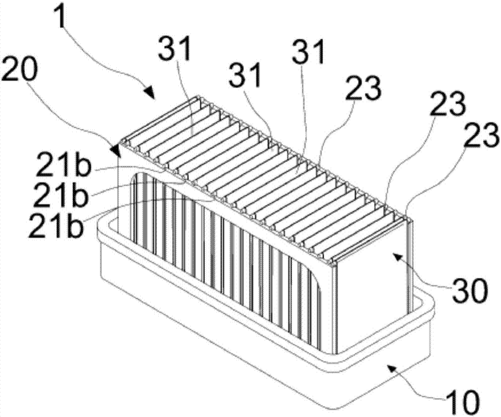
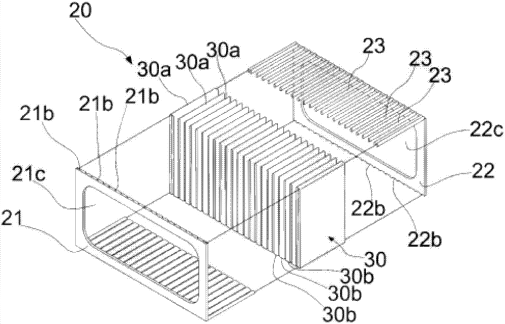
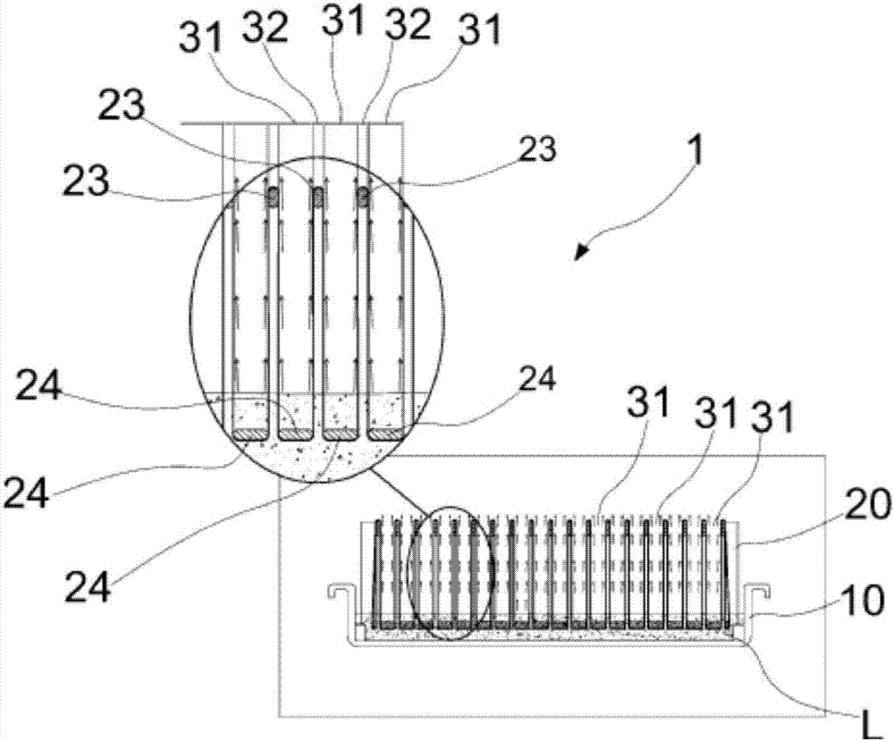
[0036] figure 1 and figure 2 It is an exploded and assembled view showing the overall structure of the natural humidifier according to the first embodiment of the present invention, image 3 It is an operation state diagram showing the humidification state of the natural humidifier according to the first embodiment of the present invention, Figure 4 to Figure 7 It is an exploded and assembled view showing the overall structure of a natural humidifier according to a second embodiment of the present invention, Figure 8 It is an operation state diagram showing the humidification state of the natural humidifier according to the second embodiment of the present invention, Figure 9 to Figure 11 It is a figure which shows the laminated structure and laminated state of the natural humidifier of 1st Embod...


PUM


Abstract

The present invention relates to a naturally humidifying device having an improved assembly structure and, more particularly, to a naturally humidifying device having an improved structure, wherein an evaporation fluid, which fills an evaporation tank, is diffused over the entire surface of an unfolded evaporation cloth through the osmotic phenomenon, and the large amount of moisture, which has been diffused over the entire surface of the evaporation cloth, is naturally evaporated into air slowly, thereby promoting natural humidification.

Description

technical field [0001] The present invention relates to a natural humidifying device with an improved assembly structure. More specifically, it involves spreading the evaporating fluid filled in the evaporating tank on the unfolded integral evaporating cloth through the phenomenon of osmotic pressure, and spreading the evaporative fluid on the integral evaporating cloth. A large amount of water on the evaporation cloth slowly and naturally evaporates in the air, thereby performing natural humidification and a natural humidification device with an improved assembly structure. Background technique [0002] Recently, commercial and residential buildings, schools, small and medium-sized residential facilities, etc. have switched from the existing central system to decentralized air-conditioning systems using electric heat pump systems or gas engine-driven heat pump systems. [0003] In addition, these facilities are equipped with ventilation devices equipped with heat exchange f...

Claims


Application Information

Patent Timeline
IPC IPC(8): F24F6/04
CPCF24F6/04F24F6/043F24F2006/046
Inventor 南大坤
Owner 南大坤
Why Eureka
Try Eureka