
Energy imaging with generally constant energy separation

一种成像、能量的技术,应用在成像系统领域,能够解决影响有效重构扫描图像、调制管电流不理想波形等问题

Active Publication Date: 2017-08-29
GENERAL ELECTRIC CO
View PDF4 Cites 5 Cited by
  • Summary
  • Abstract
  • Description
  • Claims
  • Application Information

AI Technical Summary

Problems solved by technology

In other words, modulating the tube current during a dual-energy scan may result in a non-ideal waveform, which may affect the ability to effectively reconstruct the scanned image

Method used


Image

  • Energy imaging with generally constant energy separation
  • Energy imaging with generally constant energy separation
  • Energy imaging with generally constant energy separation

Examples


Embodiment Construction

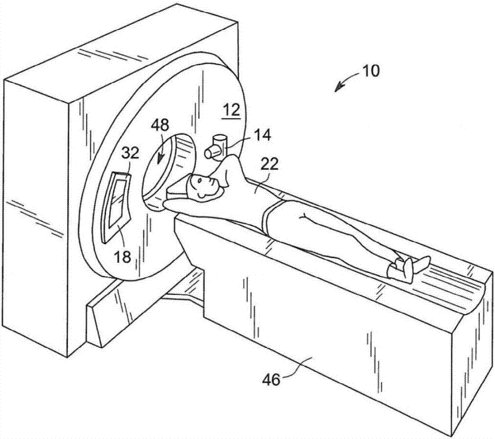
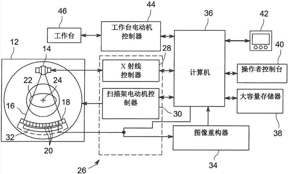
[0022] now refer to figure 1 , an exemplary computed tomography (CT) imaging system 10 is shown including a gantry 12 that may represent a "third generation" CT scanner. The gantry 12 includes an X-ray source 14 that projects a polychromatic beam of X-rays 16 towards a detector assembly 18 on the opposite side of the gantry 12 . Typically, a collimator may be an integral part of the detector assembly 18 . Such as figure 2 As shown, the detector assembly 18 may be formed from a plurality of detectors 20 and a data acquisition system (DAS) 32 . A plurality of detectors 20 sense projected X-rays passing through a patient 22 or object, and a DAS 32 converts the corresponding data into digital signals for subsequent processing. Each detector 20 generates an analog electrical signal representative of the intensity of the incident X-ray beam, and thus the intensity of the beam attenuated through the patient 22 . During a scan to acquire X-ray projection data, the gantry 12 and ...


PUM


Abstract

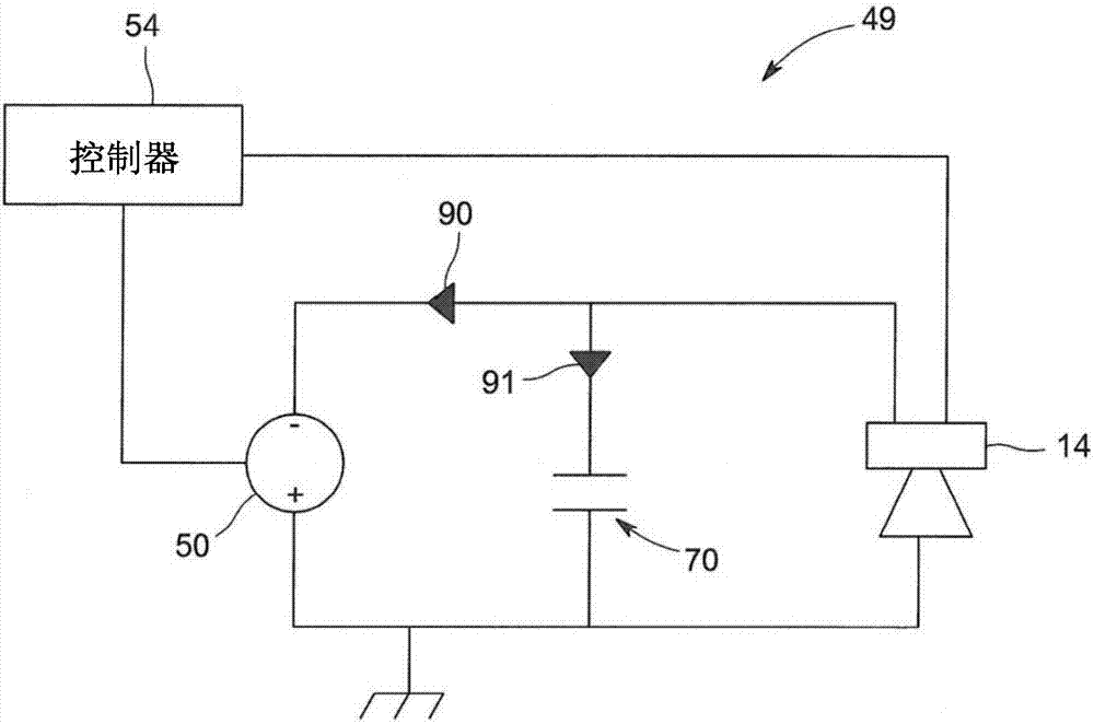
The present inventors have recognized that fall times between high-kV to low-kV levels (during a dual energy or fast-kV energy scan) are linked to the discharge of HV (high voltage) capacitance. In an embodiment of the invention, a high voltage generator may be activated during fall transitions from first to second energy levels in order to substantially maintain a predetermined fall transition time. Accordingly, substantially equal energy distributions between high-kV and low-kV levels may be achieved.

Description

[0001] Cross References to Related Applications [0002] This international patent application filed under the Patent Cooperation Treaty (PCT) claims priority to U.S. Application No. 14 / 658,913, filed March 16, 2015, and U.S. Application No. 62 / 098,001, filed December 30, 2014, They are hereby incorporated by reference in their entirety. technical field [0003] The present invention relates generally to imaging systems, and more particularly to high voltage generators for imaging systems. Background technique [0004] Computed tomography (CT) is an x-ray medical imaging procedure that enables the use of multiple two-dimensional (2D) images acquired around a patient or subject to obtain a three-dimensional (3D) image of the patient or subject. In CT, the use of dual energy imaging is known to obtain material signatures and / or reduce artifacts by utilizing two scans of a patient or subject at different voltage / energy levels ("low kV" and "high kV") . [0005] During a sin...

Claims


Application Information

Patent Timeline
Patent Type & Authority Applications(China)
IPC IPC(8): G01N23/04H05G1/58
CPCG01N23/046H05G1/58A61B6/032A61B6/482H03K17/00H05G1/10
Inventor J-F.拉鲁瓦J.布劳亚A.加德涅U.维曼M.弗伦特拉
Owner GENERAL ELECTRIC CO
Learn More