
Cleaning dust return system for floor washing machine

A washing machine and cleaning brush technology, applied in the direction of cleaning carpets, cleaning floors, manual sweeping machines, etc., can solve the problems of large power consumption, large energy proportion, flying dust, etc., to achieve reduced power consumption, convenient operation, and manufacturing low cost effect

Pending Publication Date: 2017-09-01
YANGZHOU JINWEI ENVIRONMENTAL PROTECTION TECH CO LTD
View PDF0 Cites 0 Cited by
  • Summary
  • Abstract
  • Description
  • Claims
  • Application Information

AI Technical Summary

Problems solved by technology

Such technical means have the following disadvantages: first, the power consumption is large, it is necessary to drive the sweeping brush to rotate at a high speed, and the fan is also required to rotate continuously, wherein the energy consumed by the fan operation accounts for a large proportion; second, it is inconvenient to discharge dust; Third, when the brush rotates at high speed, it will cause dust to fly

Method used


Image

  • Cleaning dust return system for floor washing machine
  • Cleaning dust return system for floor washing machine
  • Cleaning dust return system for floor washing machine

Examples


Embodiment Construction

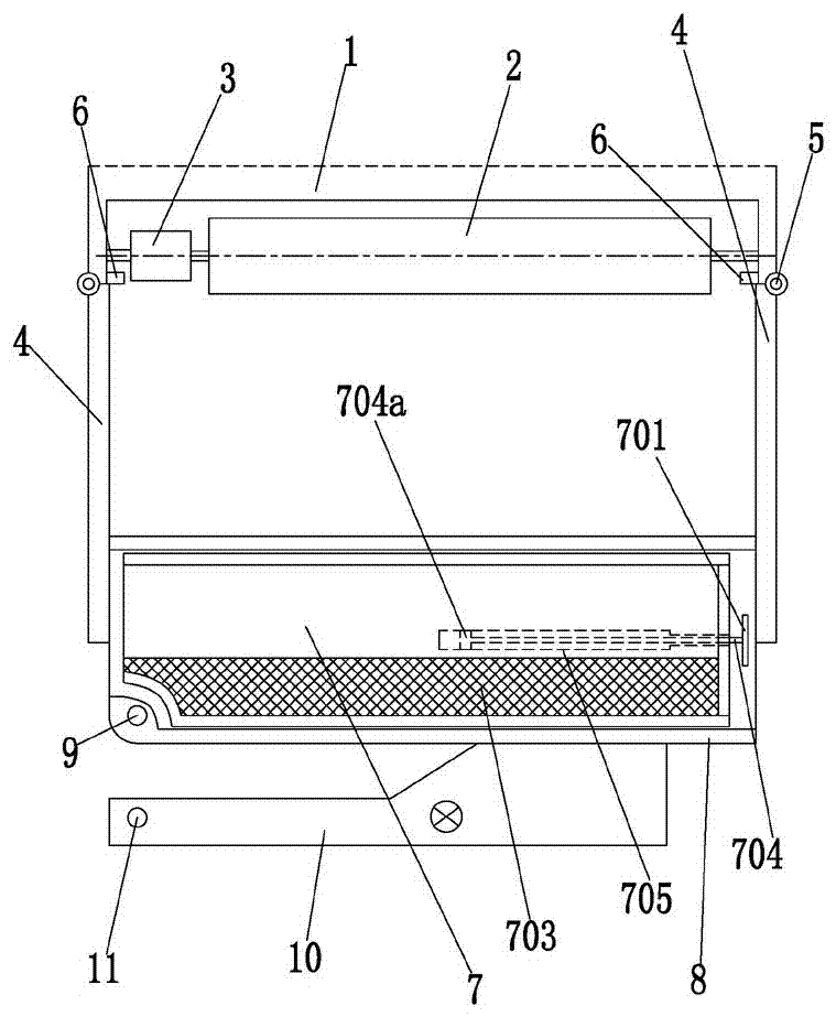
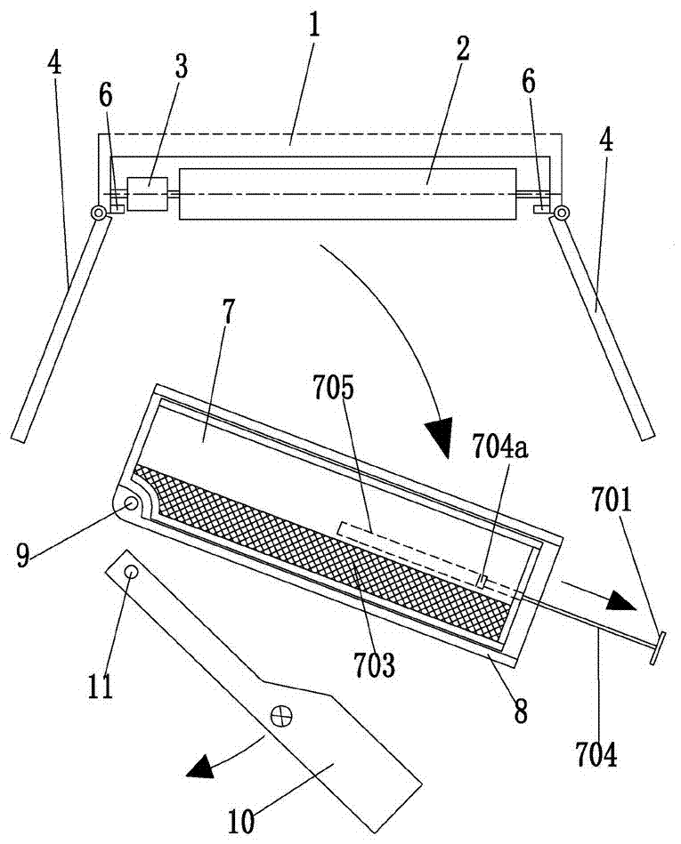
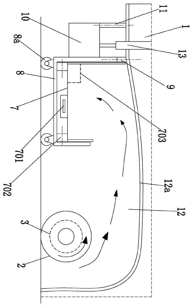
[0019] Such as Figure 1-3 As shown, a cleaning and dust return system for a floor washing machine includes a frame 1, a cleaning brush 2, a brush driving mechanism 3 for driving the cleaning brush 2 to rotate at high speed, and a dust return bin with a closed structure The chamber 12 also includes two sets of sealing assemblies that respectively seal the two sides of the dust return chamber 12, and also includes a movable base 8, a first rotating shaft 9, and is detachably installed on the movable base 8 for collecting dust, The drawable recovery bin 7 with an open upper end also includes a movable limit seat 10 , a second rotating shaft 11 , and a locking assembly 13 .

[0020] The sealing assembly includes a sealing door 4 , a door hinge shaft 5 , and a door lock 6 for locking the position of the sealing door 4 . One end of the sealing door 4 is rotatably mounted on the frame 1 through the door hinge shaft 5 .

[0021] The cleaning brush 2 is located in the dust return cha...


PUM


Abstract

The invention discloses a cleaning dust return system for a floor washing machine in the technical field of floor washing machines. The cleaning dust return system comprises a rack, a sweeping brush, a sweeping brush driving mechanism, a dust return bin, two seal assemblies, a movable base, a first rotating shaft, a withdrawable recovery bin, a movable limiting seat, a second rotating shaft, and a locking assembly. Each seal assembly comprises a sealing door, a door hinge shaft, and a door locking member for locking the position of the sealing door. One end of the sealing door is rotatably mounted on the frame by means of the door hinge shaft. The sweeping brush is located in the dust return bin. The withdrawable recovery bin is placed on the movable base. The movable limiting seat is locked on the rack through the locking assembly, and just presses against the movable base when locked by the locking assembly. When the sealing door is locked by the door locking member, the free end of the sealing door just props against the movable base. The power consumption is significantly reduced, and dust pouring is facilitated.

Description

technical field [0001] The invention relates to the technical field of floor washing machines, in particular to a cleaning and dust return system for floor washing machines. Background technique [0002] At present, many scrubbers are equipped with dry sweeping mechanisms. The most widely used technical solution is as follows: use the high-speed rotation of the sweeping brush to sweep the dust on the ground to the negative pressure suction port, and use the negative pressure source to suck the dust away. Such technical means have the following disadvantages: first, the power consumption is large, it is necessary to drive the sweeping brush to rotate at a high speed, and the fan is also required to rotate continuously, wherein the energy consumed by the fan operation accounts for a large proportion; second, it is inconvenient to discharge dust; Its three, sweeping brush can cause dust to fly when rotating at high speed. Contents of the invention [0003] The object of the ...

Claims


Application Information

Patent Timeline
IPC IPC(8): A47L11/24A47L11/30A47L11/40
CPCA47L11/24A47L11/302A47L11/40A47L11/4016A47L11/4025A47L11/4094
Inventor 陈彪刘献栋刘銮敏张恒刘玉红陆禹
Owner YANGZHOU JINWEI ENVIRONMENTAL PROTECTION TECH CO LTD
Learn More