
Hydraulic cylinder

A hydraulic cylinder and cylinder barrel technology, applied in the field of fluid pressure actuators, can solve problems such as small axial force, potential safety hazards, and easy damage, and achieve the effect of convenient integrated design, easy design, and simple structure

Active Publication Date: 2017-09-01
宁波中天联合机电制造有限公司
View PDF5 Cites 3 Cited by
  • Summary
  • Abstract
  • Description
  • Claims
  • Application Information

AI Technical Summary

Problems solved by technology

However, there is still a shortcoming in the hydraulic cylinder of the above-mentioned structure in the actual application process: if the piston rod of the above-mentioned hydraulic cylinder is to be fully retracted, not only the external oil circuit system is required to discharge the oil, but also the cockpit of the vehicle needs to be used to control the oil. Its downforce can only be matched, but when the cockpit of the vehicle is almost completely lowered and restored to its original position, the hydraulic cylinder is close to the horizontal state at this time, and the axial force exerted on the piston rod of the hydraulic cylinder by the downforce of the cockpit of the vehicle is very small. As a result, it is easy to cause the piston rod of the hydraulic cylinder to be unable to be fully retracted, and the cockpit of the vehicle cannot be completely put down, which poses a safety hazard; and when the vehicle is running, the external oil circuit system is usually closed, and once the external oil circuit system is closed, The hydraulic control check valve prevents the oil in the cylinder of the hydraulic cylinder from flowing out. At this time, when the cockpit of the vehicle bumps up and down during driving, it will frequently exert force on the hydraulic cylinder, and because the hydraulic cylinder The oil in the cylinder cannot be discharged, so the piston rod cannot be retracted, so the hydraulic cylinder is easily damaged under frequent impact

Method used


Image

  • Hydraulic cylinder
  • Hydraulic cylinder

Examples


Embodiment Construction

[0026] The hydraulic cylinder of the present invention will be further described in detail below in conjunction with the accompanying drawings and specific embodiments.

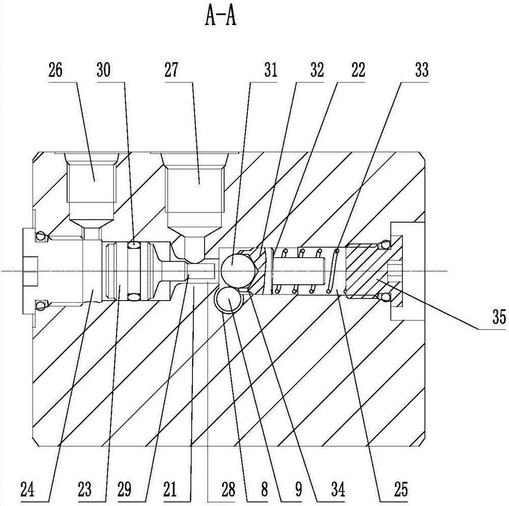
[0027] Such as figure 1 with figure 2As shown, the hydraulic cylinder of the present invention includes a cylinder bottom 1, a cylinder barrel 2, a piston rod 3 and a hydraulic control check valve 4. One end of the cylinder barrel 2 is connected to the cylinder bottom 1, and the piston rod 3 is telescopically inserted in the cylinder barrel 2. A first sealing device 5 is provided between the other end of the cylinder 2 and the piston rod 3, the hydraulic control check valve 4 is arranged on the bottom of the cylinder 1, and the piston rod 3 is provided with a During the process, the hydraulic control check valve 4 can be opened, and after the piston rod 3 is fully retracted, the hydraulic control check valve 4 can always be kept open, so that the external oil circuit system can communicate with the inner ca...


PUM


Abstract

The invention relates to a hydraulic cylinder. The hydraulic cylinder comprises a cylinder bottom (1), a cylinder barrel (2), a piston rod (3) and a hydraulic control one-way valve (4); one end of the cylinder barrel (2) is connected with the cylinder bottom (1); the piston rod (3) is telescopically inserted in the cylinder barrel (2); the hydraulic control one-way valve (4) is arranged on the cylinder bottom (1); and the piston rod (3) is provided with an unlocking mechanism capable of opening the hydraulic control one-way valve (4) in the process of shrinking the piston rod (3) back into the cylinder barrel (2) and capable of always keeping the hydraulic control one-way valve (4) in an open state to conduct an external oil way system with an inner cavity of the cylinder barrel (2) after the piston rod (3) totally shrinks back. The hydraulic cylinder has the following advantages: the piston rod is convenient to totally shrink back, so that a vehicle driving cabin can be totally put down, and the safety is high; and when the vehicle driving cabin jolts up and down in the vehicle driving process, the impact force to the hydraulic cylinder can be greatly reduced, the quality of the hydraulic cylinder can be guaranteed, and the damage of the hydraulic cylinder is effectively prevented.

Description

technical field [0001] The invention relates to a fluid pressure actuator, in particular to a hydraulic cylinder. Background technique [0002] A hydraulic cylinder is a hydraulic actuator that converts hydraulic energy into mechanical energy and performs linear reciprocating or oscillating motion. It is simple in structure and reliable in operation. When it is used to realize reciprocating motion, the deceleration device can be eliminated, and there is no transmission gap, and the motion is stable. Therefore, it is widely used in various mechanical hydraulic systems. At present, hydraulic cylinders are installed at the bottom of the cockpits of existing engineering vehicles, trucks and other vehicles. When the cockpits of vehicles such as engineering vehicles and trucks need to be opened, the hydraulic cylinders can push up and support one side of the cockpit. Existing hydraulic cylinders generally include a cylinder barrel, a cylinder bottom and a piston rod, and a hydrau...

Claims


Application Information

Patent Timeline
IPC IPC(8): F15B15/16F15B15/20F16K15/04
CPCF15B15/1457F15B15/16F15B15/20F15B15/202F16K15/044
Inventor 舒平国江承书戴洪辉
Owner 宁波中天联合机电制造有限公司
Learn More