Data acquisition device and excitation state service life measurement method based on excitation state service life measurement of frequency count card
A technology of frequency counting and data acquisition, used in instruments and other directions
- Summary
- Abstract
- Description
- Claims
- Application Information
AI Technical Summary
Problems solved by technology
Method used
Image
Examples
Embodiment 1
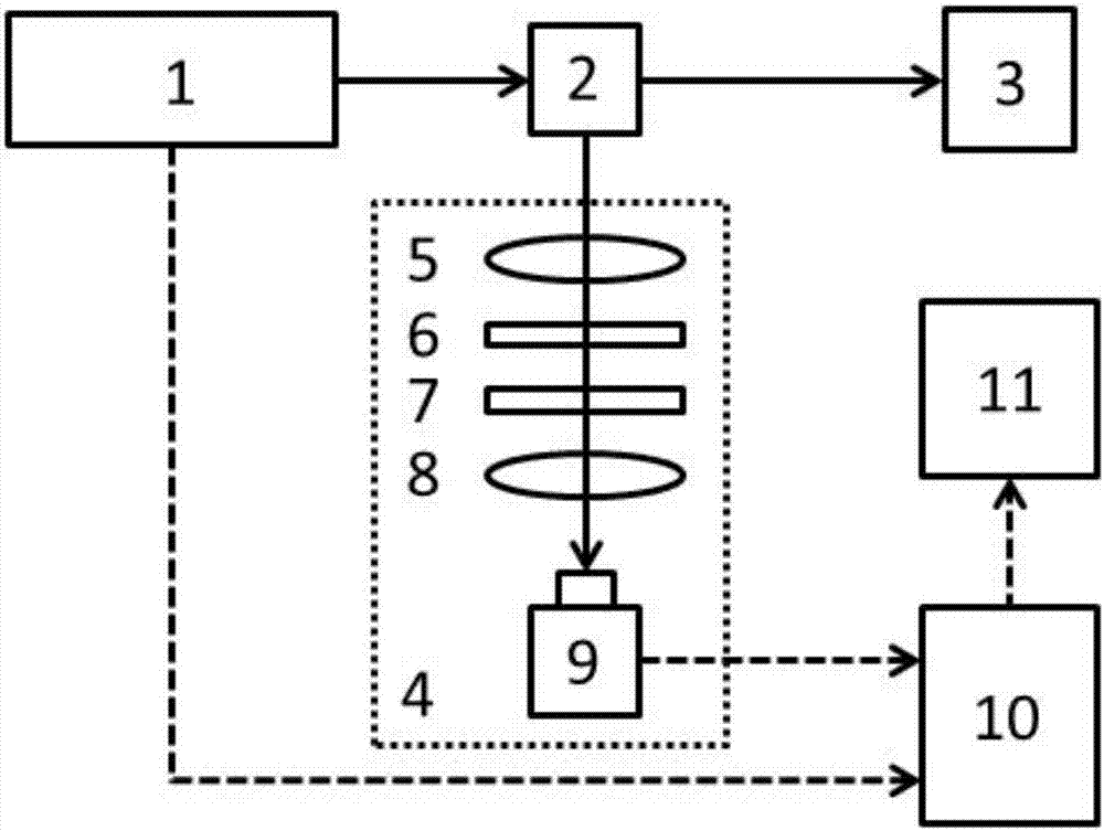
[0025] Embodiment 1: a kind of data acquisition device based on the excited state lifetime measurement of frequency counting card, described device comprises pulse excitation light source 1, sample cell 2, fluorescence collection system 4, the light-emitting port of described excitation light source 1 and fluorescence collection system Facing the sample cell, in order to obtain the time interval between the photon pulse signal and the excitation light pulse signal, the device also includes a data acquisition system, the data acquisition system includes a frequency counter card, which is connected to the signal synchronous output of the pulse excitation light source 1 pin, and is connected with the signal output pin of the photodetector of the light collector 3.
[0026] The device also includes a light collector, and the light emitting port of the excitation light source 1 is in a straight line with the center of the sample pool 2 and the light collector 3 . The purpose is to ...
Embodiment 2
[0036] Embodiment 2: The purpose of this embodiment is to provide a method and device for measuring excited state lifetimes that are compatible with a wide range of lifetimes (such as hundreds of picoseconds to milliseconds) and are cheaper, that is, they can be used to measure short-lived fluorescence samples, and also for long-lived phosphorescent samples.
[0037] The excited state lifetime measurement method based on the frequency counting card includes the following steps:
[0038] 1) Excite the sample to be tested with pulsed light at a high repetition rate to generate photoluminescence;
[0039] 2) Detecting the photoluminescent signal of the sample, using a frequency counting card to measure the time interval (time difference) between the detected photon pulse signal and the excitation light pulse signal;
[0040] 3) dividing the measured photon time difference into various time intervals, and assigning photons with different time difference data into corresponding ti...
Embodiment 3
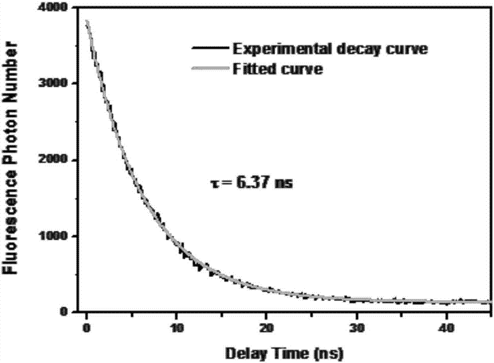
[0054] Example 3: For the investigation of the excited state lifetime measuring device described in the present invention when measuring short-lived samples, No. 1 short-lived sample (its fluorescence peak position is about 610nm) was used for testing. First, put the cuvette containing sample No. 1 into the sample cell, use picosecond pulse laser (405nm) to excite the sample, and set the laser repetition frequency to 20MHz; use a 405nm notch filter, and a fluorescence filter of 610nm Narrow-band filter, light-receiving and converging lens all adopt 60mm focal length lens, the measured fluorescence decay curve of this sample is as follows figure 2 shown. Using a single exponential decay function I(t)=I 0 exp(-t / τ)+c (where τ is the fluorescence lifetime of the sample to be tested, and c is the background noise) performs data fitting on the decay curve, and it can be obtained that the fluorescence lifetime of the sample to be tested is about τ=6.37ns .
PUM
 Abstract
Description
Claims
Application Information
 - R&D
- Intellectual Property
- Life Sciences
- Materials
- Tech Scout
- Unparalleled Data Quality
- Higher Quality Content
- 60% Fewer Hallucinations
Browse by: Latest US Patents, China's latest patents, Technical Efficacy Thesaurus, Application Domain, Technology Topic, Popular Technical Reports.
© 2025 PatSnap. All rights reserved.Legal|Privacy policy|Modern Slavery Act Transparency Statement|Sitemap|About US| Contact US: help@patsnap.com


