Electronic switch circuit

An electronic switch and switching circuit technology, applied in electronic switches, circuits, electrical components, etc., can solve the problems of radiation response, short life of isolated electromagnetic relays, electromagnetic waves of mechanical noise, etc., to achieve fast response, no mechanical noise, and short time. Effect

Inactive Publication Date: 2017-09-01
GUANGZHOU SHIYUAN ELECTRONICS CO LTD +1
View PDF3 Cites 1 Cited by
  • Summary
  • Abstract
  • Description
  • Claims
  • Application Information

AI Technical Summary

Problems solved by technology

[0005] In order to solve the technical problems of short life, mechanical noise and electromagnetic wave radiation and slow response of the isolated electromagnetic relay, the embodiment of the present invention proposes an electronic switch circuit

Method used


Image

  • Electronic switch circuit
  • Electronic switch circuit
  • Electronic switch circuit

Examples


Embodiment 1

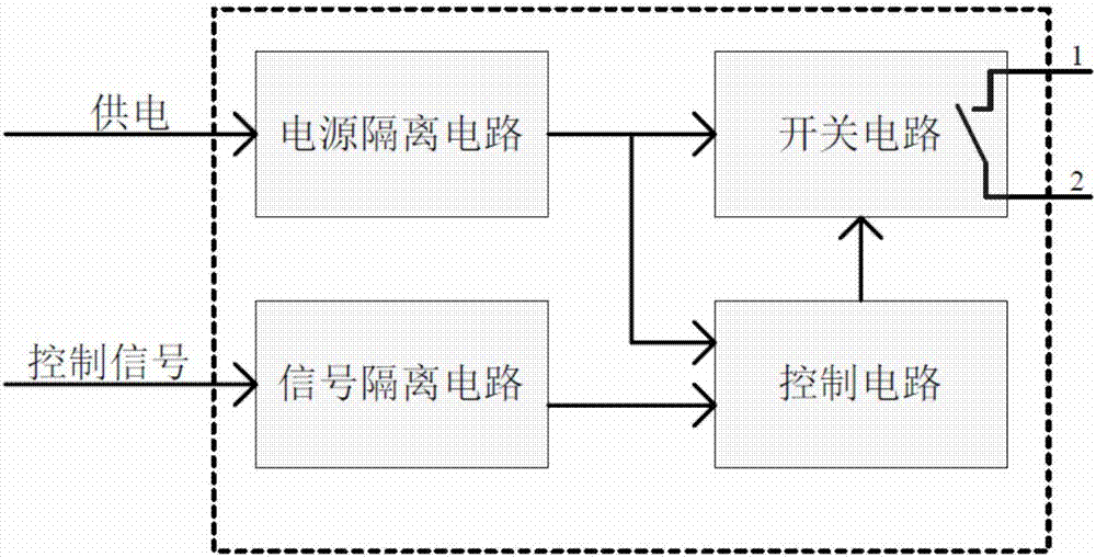
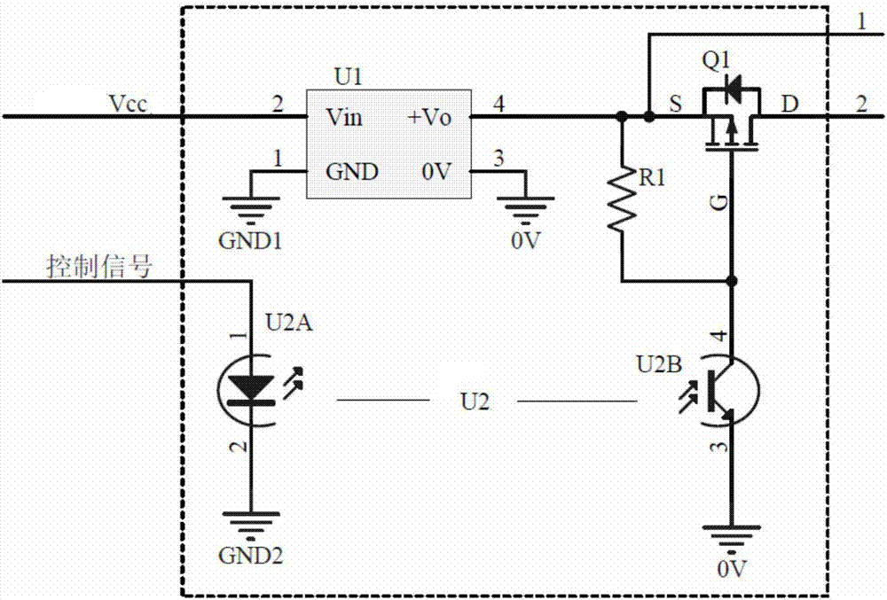
[0043] The electronic switch circuit proposed in Embodiment 1 of the present invention is as follows: image 3 As shown, the electronic switch circuit includes: a power isolation circuit U1, a signal isolation circuit U2, a switch circuit Q1 and a control circuit, wherein the control circuit includes a first resistor R1, the signal isolation circuit is a photoelectric coupling device, and the switch circuit Q1 is a P-channel field effect tube.

[0044] The Vin terminal of the power isolation circuit U1 is connected to the power supply Vcc, the GND terminal is connected to the first reference ground GND1, the +Vo terminal is respectively connected to one end of the first resistor R1 and the source S of the switch circuit Q1, the 0V terminal is connected to the second reference ground 0V, and the +Vo terminal is connected to the second reference ground 0V. The second reference ground 0V is different from the first reference ground GND1 to prevent signal interference.

[0045] T...

Embodiment 2

[0057] In this embodiment, on the basis of Embodiment 1, a driving circuit is added.

[0058] The electronic switch circuit proposed in this embodiment is as Figure 5 As shown, it includes: power isolation circuit U51, signal isolation circuit U53, switch circuit Q51 and control circuit, and also includes a first drive circuit and a second drive circuit, wherein the control circuit includes a second resistor R52, and the signal isolation circuit U53 is a photocoupler device, the switch circuit Q51 is a P-channel field effect transistor.

[0059] The power input terminal of the power isolation circuit U51, that is, the Vin terminal is connected to the first power supply Vcc, the GND terminal is connected to the first reference ground GND1, and the power output terminal, namely the +Vo terminal, is respectively connected to one end of the first resistor R51, one end of the second resistor R52 and the switch The source S, 0V of the circuit Q51 is connected to the second referen...

Embodiment 3

[0074] On the basis of Embodiment 1, the embodiment of the present invention not only adds a driving circuit, but also adds a rectifying circuit, so that the electronic switching circuit is suitable for both DC power supply and AC power supply.

[0075] The electronic switch circuit proposed by the embodiment of the present invention is as Figure 6 As shown, the electronic switch circuit includes: a power isolation circuit U61, a signal isolation circuit U62, a switch circuit Q61, a control circuit, a drive circuit and a rectifier circuit, wherein the control circuit includes a first resistor R61, the signal isolation circuit is a photocoupler, and the switch Circuit Q61 is an N-channel field effect transistor.

[0076] The driving circuit includes a second resistor R62, a PNP transistor Q62 and a third resistor R63. One end of the second resistor R62 is connected to the emitter E of the PNP transistor Q62, and the other end is respectively connected to the base B of the PNP...


PUM


Abstract

The invention relates to an electronic switch circuit, comprising the following components: a power isolation circuit, a signal isolation circuit, a control circuit and a switch circuit, wherein a power supply is separately input to the switch circuit and the control circuit after being processed by the power isolation circuit; and a control signal is input to the control circuit after being processed by the signal isolation circuit, and the switch circuit is disconnected or closed under the control of the control circuit to achieve the function of an electronic switch. According to the electronic switch circuit disclosed by the embodiment of the invention, the interaction between the control signal and the controlled power supply or signals can be avoided; and the electronic switch circuit is long in service life, does not have mechanical noises, and is fast in response.

Description

technical field [0001] The invention belongs to the field of electronic circuits, and in particular relates to an electronic switch circuit. Background technique [0002] Controlled switches are often used in existing electronic circuits, and the closing and opening of the controlled switches are controlled by signals. Some circuits need to use isolated controlled switches for electrical safety (such as avoiding electric shock) or for signal isolation (such as eliminating the mutual influence between the control signal and the controlled power supply or signal). [0003] The isolated electromagnetic relay is a common electronic control circuit or electronic control device that can be used as an isolated controlled switch. It uses a energized coil to generate a magnetic field, and then attracts a movable conductive piece to control the switch on and off. figure 1 The isolated electromagnetic relay shown is a moving-close electromagnetic relay, where figure 1 The components ...

Claims


Application Information

Patent Timeline
Patent Type & Authority Applications(China)
IPC IPC(8): H03K17/687H03K17/785H03K17/041H03K17/16
CPCH03K17/04106H03K17/162H03K17/687H03K17/785
Inventor 梁军徐章龙杨莲科
Owner GUANGZHOU SHIYUAN ELECTRONICS CO LTD
Why Eureka
Try Eureka