
Line protection and travelling wave fault location integrated device and travelling wave information inter-station communication method thereof

A traveling wave ranging and line protection technology, applied in the direction of adjustment of transmission mode, transmission modification based on link quality, digital transmission system, etc., can solve the problems of increasing communication costs, maintenance and management costs, and increasing engineering debugging complexity. Achieve the effect of reducing communication costs and maintenance management costs, improving integration and ease of use, and simplifying engineering debugging

Inactive Publication Date: 2017-09-01
CHINA SOUTHERN POWER GRID COMPANY +2
View PDF4 Cites 2 Cited by
  • Summary
  • Abstract
  • Description
  • Claims
  • Application Information

AI Technical Summary

Problems solved by technology

Although it is possible to allocate a dedicated channel for the traveling wave ranging function, or configure an inter-station network communication channel, it will increase the communication cost and maintenance management cost, and increase the complexity of engineering debugging

Method used


Image

  • Line protection and travelling wave fault location integrated device and travelling wave information inter-station communication method thereof
  • Line protection and travelling wave fault location integrated device and travelling wave information inter-station communication method thereof
  • Line protection and travelling wave fault location integrated device and travelling wave information inter-station communication method thereof

Examples


Embodiment Construction

[0011] The embodiment of the present invention provides a method for increasing the collection of traveling wave signals in the transmission line relay protection device. The specific implementation of the embodiment of the present invention is as follows:

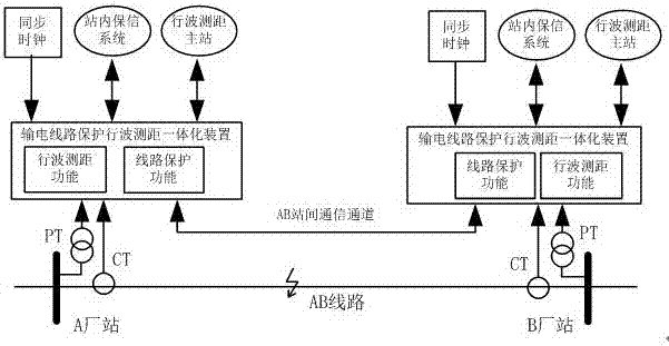
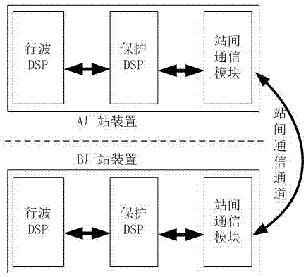
[0012] The line protection traveling wave distance measuring integrated device of the present invention has the transmission line relay protection function and the traveling wave distance measuring function, including a traveling wave DSP module, a protection DSP module, an inter-station communication module, a protection DSP module and a traveling wave DSP module Both achieve information interaction with the opposite end through the same inter-station communication module and inter-station communication channel.

[0013] [c1] In this embodiment, the traveling wave DSP module includes a traveling wave communication module. In this embodiment, the protection DSP module includes a protection communication module.

[0014] I...


PUM


Abstract

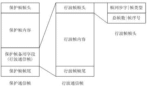
The invention discloses a line protection and travelling wave fault location integrated device and a travelling wave information inter-station communication method thereof. The method is to enable a protected DSP module and a travelling wave DSP module to realize information interaction with an opposite end through an inter-station communication channel based on an existing inter-station communication module and an existing inter-station communication channel of a power transmission line protection device. A travelling wave communication module transmits travelling wave information by utilizing a standby field of a protected communication data frame. Complete travelling wave information is divided into multiple frames based on the length of the standby field for transmission; a travelling wave communication reception module can splice multi-frame content into complete travelling wave information based on the frame sequential number and the total frame number in the frame head of the travelling wave frame. By adoption of the method, although the protected communication and the travelling wave communication share a communication link, the travelling wave communication does not affect the bandwidth and reliability of the protected communication. After the method is adopted, extra configuration of a dedicated channel or network or network communication channel is unnecessary for a travelling wave fault location function, the communication cost and the maintenance management cost can be reduced, and simplification of the engineering debugging is facilitated.

Description

technical field [0001] The invention relates to power grid protection and automation technology, in particular to a line protection traveling wave distance measuring integrated device and a traveling wave information inter-station communication method. Background technique [0002] Currently widely used transmission line protection devices use the impedance method for fault location. This method is easily affected by the system operation mode, transition resistance, attenuated DC component and measurement error, and it is difficult to achieve accurate fault location. An effective way to improve the accuracy of line fault location is to add traveling wave ranging function to the transmission line protection device to form an integrated device for line protection traveling wave ranging, so that the monitored line can realize double-terminal traveling wave ranging and Single-ended traveling wave ranging function. Compared with single-terminal traveling wave ranging, double-ter...

Claims


Application Information

Patent Timeline
IPC IPC(8): H04L1/00H04L29/06
CPCH04L1/0006H04L69/26
Inventor 丁晓兵史泽兵陈玉林刘千宽余江张弛徐晓春张青春朱晓彤陈宏山陈朝晖陆金凤吕航沈军
Owner CHINA SOUTHERN POWER GRID COMPANY
Learn More