
Amorphous strip forming device

A forming device and technology for amorphous strips, applied in the field of supporting components for amorphous strip production equipment, can solve problems such as increased supporting costs, reduced qualification rates, and increased costs, so as to ensure product qualification rates and yields, and reduce Difficulty in cooling and the effect of reducing energy consumption of equipment

Pending Publication Date: 2017-09-05
QINGDAO YUNLU ADVANCED MATERIALS TECH CO LTD
View PDF6 Cites 2 Cited by
  • Summary
  • Abstract
  • Description
  • Claims
  • Application Information

AI Technical Summary

Problems solved by technology

[0002] In the existing processing and production process of amorphous strip, usually the molten alloy flows out from the nozzle of the spray bag and then sprays out along the side where the grabbing equipment is located. Consistent, so it is referred to as positive spraying. The following problems exist in this strip-making method: First, the wrap angle of the strip on the cooling roll is less than 90° during the strip-making process. To ensure that the strip has a sufficient cooling length on the cooling roll, it needs to be cooled The diameter of the roll is large, and the diameter of the cooling roll is generally greater than 1200mm, which greatly increases the cost of the cooling roll. The temperature balance itself takes a long time, the strip adjustment time is long, the material waste is serious and the production progress is seriously delayed. The problem caused by the large diameter of the cooling roll is that the cooling area needs to be greatly increased under the condition of ensuring a certain uniform cooling requirement. , the amount of cooling water required is also greatly increased, which not only increases the corresponding supporting costs, but also increases the energy consumption of the equipment; second, in this way, pressure rollers are set at the strip forming end to control the operation accuracy of the downstream grabbing device, And the pressure roller is needed to ensure that the strip can obtain a certain cooling length on the cooling roller during the coiling and retreating process of the strip, which leads to the need to interrupt the strip and raise the pressure roller to the initial position before grabbing again if the strip is grabbed again. This leads to the lack of quality monitoring in the strip production process, and the pass rate is greatly reduced

Method used


Image

  • Amorphous strip forming device

Examples


Embodiment Construction

[0016] The core of the present invention is to provide an amorphous strip forming device, the amorphous strip forming device has a better cooling and forming effect on the amorphous strip, and its energy consumption is low, and its product qualification rate and yield rate are relatively high. high.

[0017] In order to enable those skilled in the art to better understand the solution of the present invention, the present invention will be further described in detail below in conjunction with the accompanying drawings and specific embodiments.

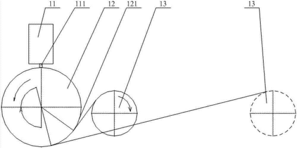
[0018] Please refer to figure 1 , figure 1 It is a schematic structural diagram of an amorphous strip forming device provided by a specific embodiment of the present invention.

[0019] In a specific embodiment, the amorphous strip forming device provided by the present invention includes a spray tape bag 11, the bottom of the spray tape bag 11 has a nozzle 111, and a cooling roll 12 is arranged below the nozzle 111 to rotate with a ...


PUM


Abstract

The invention discloses an amorphous strip forming device. The amorphous strip forming device comprises a strip spraying bag. A nozzle is arranged at the bottom of the strip spraying bag. A cooling roller is rotationally arranged below the nozzle in a fixed-axis manner. A grabbing device is arranged on one side of the cooling roller, and the movement direction of a top blanking forming position of the cooling roller is directed at the side away from the grabbing device. A stripping device matched with a strip is arranged on the cooling roller. The amorphous strip forming device is good in amorphous strip cooling forming effect and is low in energy consumption, and the product qualification rate and the yield of the device are high.

Description

technical field [0001] The invention relates to the technical field of supporting components of amorphous strip production equipment, in particular to an amorphous strip forming device. Background technique [0002] In the existing processing and production process of amorphous strip, usually the molten alloy flows out from the nozzle of the spray bag and then sprays out along the side where the grabbing equipment is located. Consistent, so it is referred to as positive spraying. The following problems exist in this strip-making method: First, the wrap angle of the strip on the cooling roll is less than 90° during the strip-making process. To ensure that the strip has a sufficient cooling length on the cooling roll, it needs to be cooled The diameter of the roll is large, and the diameter of the cooling roll is generally greater than 1200mm, which greatly increases the cost of the cooling roll. The temperature balance itself takes a long time, the strip adjustment time is l...

Claims


Application Information

Patent Timeline
IPC IPC(8): B22D11/06
CPCB22D11/0611B22D11/0642B22D11/0694
Inventor 庞靖李庆华李晨姜宁
Owner QINGDAO YUNLU ADVANCED MATERIALS TECH CO LTD
Learn More