
A powder compacting device

A technology for pressing and forming powder, applied in the direction of material forming presses, presses, manufacturing tools, etc., can solve the problems of increased workload, cumbersome roll changing procedures, narrow sales channels for finished products, etc., to achieve the effect of improving efficiency

Active Publication Date: 2019-06-25
TAIYUAN UNIVERSITY OF SCIENCE AND TECHNOLOGY
View PDF8 Cites 0 Cited by
  • Summary
  • Abstract
  • Description
  • Claims
  • Application Information

AI Technical Summary

Problems solved by technology

Although this molding method is the most intuitive and effective, with the increasing popularity of powder molding products in industrial and other fields, as well as the special requirements for the hardness, shape and size of the product, many shortcomings of the roller molding method are exposed.
First of all, although the production efficiency of double-roll forming is very high, the yield is very low, and the procedure of changing rolls is cumbersome; secondly, the alignment accuracy of the two rolls of double-roll forming is not high, and the deviation between the double-rolls will directly affect the hardness of the product; finally There is no quantitative standard for the setting of the roller spacing for roll forming, and the roll forming needs frequent calibration and maintenance, as well as frequent cleaning, which invisibly increases a lot of workload and greatly increases production costs.
The production method of stamping forming is also common in traditional forming work, but the quantitative work in the production process is not accurate enough, resulting in a lack of compactness in the final product
On the other hand, the size and shape of traditional pressing machinery are not easy to adjust, which leads to a narrow sales channel for finished products

Method used


Image

  • A powder compacting device
  • A powder compacting device
  • A powder compacting device

Examples


Embodiment Construction

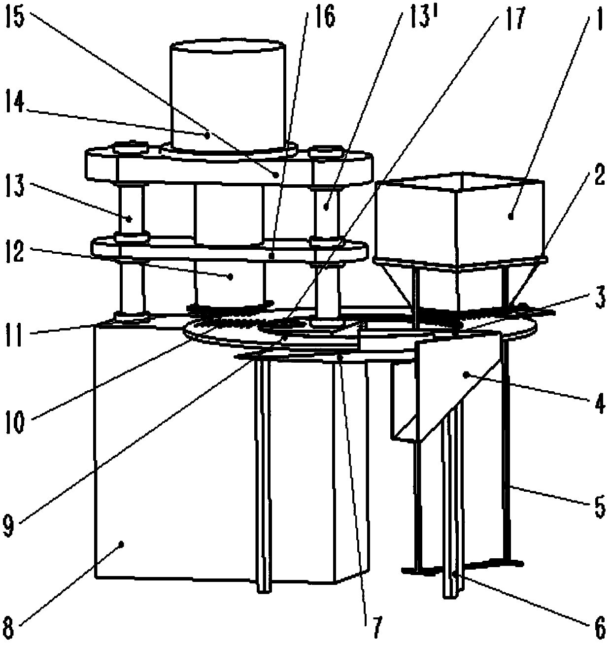
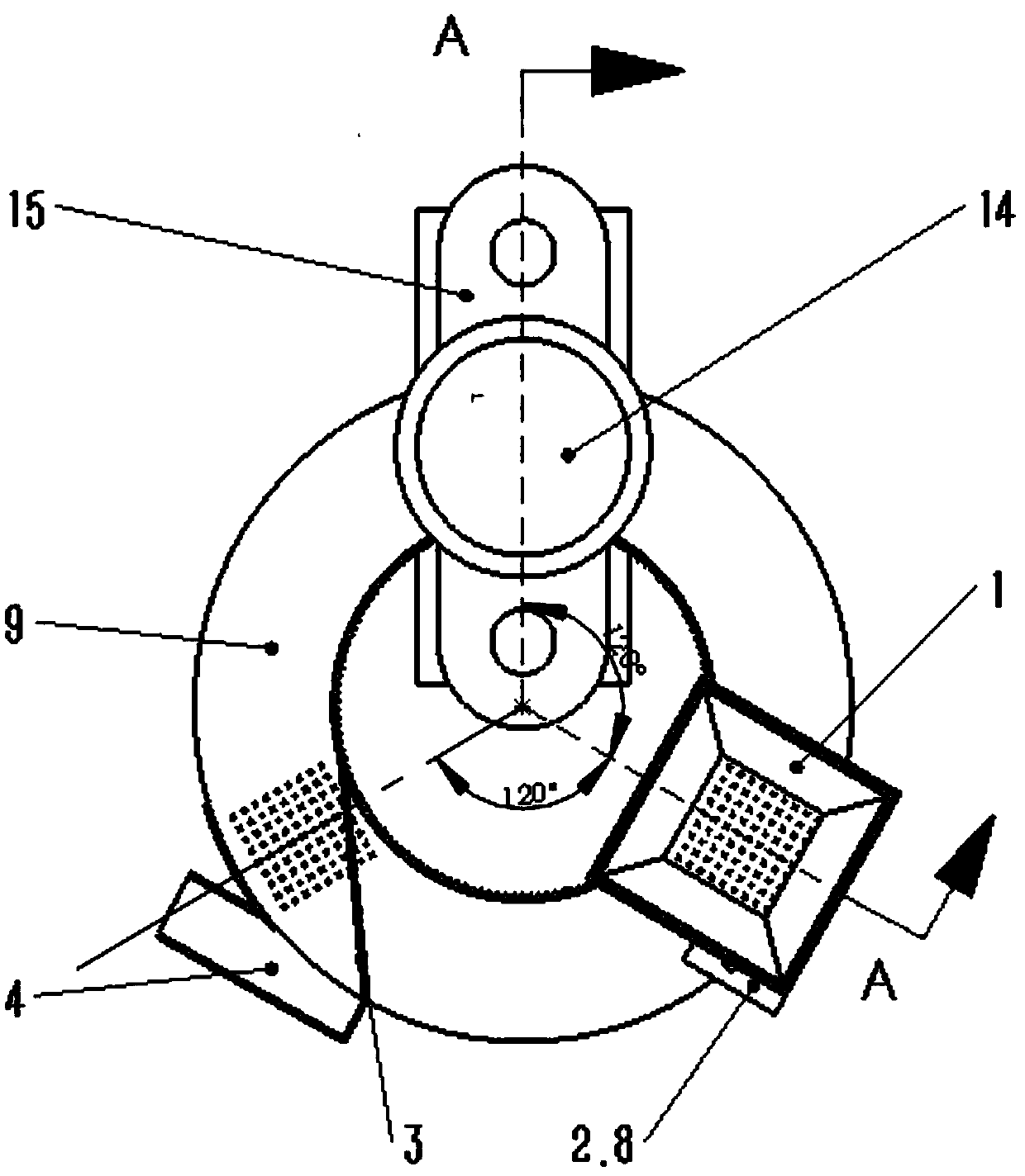
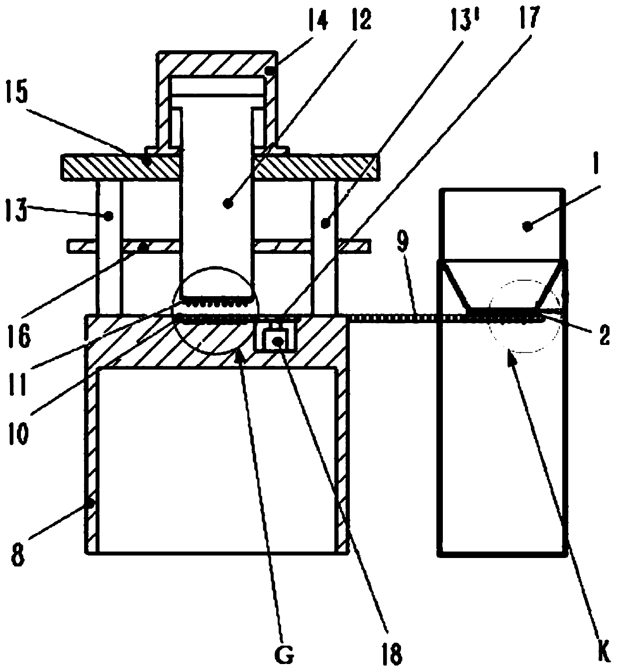
[0023] Such as figure 1 , 4 As shown in , 6, before the device is started, the powder is first added to the funnel-shaped hopper 1, and the powder will enter the quantification hole 2.11 on the quantization plate 2.1 through the feeding hole 1.1 at the bottom of the funnel-shaped hopper 1, and the quantification hole 2.11 The volume is set, at this time, start the second motor 2.7 to drive the belt drive 2.6 → drive the cam 2.5 to rotate → force the lever 2.3 to rotate → pull the quantization plate 2.1 to move laterally → the quantization hole 2.11 and the discharge hole 2.21 on the discharge plate 2.2 Align with the forming lower mold groove 10 on the rotary table 9, the quantified powder falls into the forming lower mold groove 10; start the second motor 18 to drive the rotary table 9 to rotate 120 0 , the forming lower mold groove 10 that has been filled with powder is turned to be aligned with the forming upper mold column 11, the piston cylinder 14 is opened, and the pis...


PUM


Abstract

The invention discloses a powder pressing formation device and belongs to the technical field of powder pressing formation. The powder pressing formation device is characterized in that a rotary workbench with inner teeth formed in the periphery of a center hole is supported on a machine base, formation lower die grooves are formed in the workbench face of the rotary workbench at the equal intervals of 120 degrees, and a funnel-shaped hopper, a quantization device, a formation upper die column connected with a piston rod and a finished product ejection and collection device are arranged at the upper positions corresponding to the formation lower die grooves respectively. The powder pressing formation device has the advantages that the formation lower die grooves at the trisection positions of the rotary workbench correspond to three working procedures of quantized loading, pressing formation and finished product collection to work simultaneously, the working efficiency is improved, product quality is improved through quantized loading and pressing formation, and automatic production is achieved through continuous work.

Description

technical field [0001] The invention belongs to the field of powder material compression molding, and in particular relates to a powder material compression molding device. Background technique [0002] At present, in the field of powder compression molding, the main preparations of powder compression molding are roll forming, stamping forming, and the like. For the powder molding method with no added binder and low humidity, the most commonly used method is roll molding. Although this molding method is the most intuitive and effective, with the increasing popularity of powder molding products in industrial and other fields, as well as the special requirements for the hardness, shape and size of the product, many shortcomings of the roller molding method are exposed. First of all, although the production efficiency of double-roll forming is very high, the yield is very low, and the procedure of changing rolls is cumbersome; secondly, the alignment accuracy of the two rolls ...

Claims


Application Information

Patent Timeline
Patent Type & Authority Patents(China)
IPC IPC(8): B30B11/10B30B15/30B30B15/32
CPCB30B11/10B30B15/302B30B15/32
Inventor 赵春江杨涛朱琳张飞涛王琛孙彪李光辉
Owner TAIYUAN UNIVERSITY OF SCIENCE AND TECHNOLOGY
Learn More