Emergency traction power supply system of electric motor unit

A traction power supply system, electric vehicle unit technology, applied in electric vehicles, AC induction motor traction, power management and other directions, can solve potential safety hazards, battery capacity can not meet long-term control, emergency lighting and emergency ventilation needs, on-site confusion, etc.

Pending Publication Date: 2017-09-05
CHINA RAILWAYS CORPORATION +3
View PDF6 Cites 43 Cited by
  • Summary
  • Abstract
  • Description
  • Claims
  • Application Information

AI Technical Summary

Problems solved by technology

In the state of power failure, the EMUs can only stop on the line and wait for rescue. During the rescue, the EMUs rely on their own batteries to provide power for emergency control, emergency lighting and emergency ventilation, but the existing battery capacity cannot meet the long-term requirements. Time control, emergency lighting and emergency ventilation requirements, when a power failure occurs, it is easy to cause confusion on site due to factors such as high temperature and lack of oxygen in the compartment, and there are potential safety hazards

Method used


Image

  • Emergency traction power supply system of electric motor unit
  • Emergency traction power supply system of electric motor unit
  • Emergency traction power supply system of electric motor unit

Examples


Embodiment Construction

[0027] The following will clearly and completely describe the technical solutions in the embodiments of the present invention with reference to the accompanying drawings in the embodiments of the present invention. Obviously, the described embodiments are only some, not all, embodiments of the present invention. Based on the embodiments of the present invention, all other embodiments obtained by persons of ordinary skill in the art without making creative efforts belong to the protection scope of the present invention.

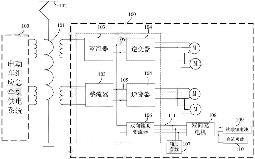
[0028] figure 1 It is a structural schematic diagram of an emergency traction power supply system for electric train units according to an embodiment of the present invention, as figure 1 As shown, the EMU emergency traction power supply system 100 includes:

[0029] The traction transformer 101 is connected to the catenary 102 through a high-voltage electrical appliance such as a pantograph, and is used for taking power from the catenary 102 and stepping dow...


PUM


Abstract

The invention discloses an emergency traction power supply system of an electric motor unit, which comprises a traction transformer used for reducing high voltage of a contact network, two rectifiers used for rectifying alternating current of secondary side windings of the traction transformer into voltage of middle direct current links, two inverters used for taking electricity from the middle direct current links and performing inversion into three-phase alternating current, a two-way auxiliary current transformer used for taking electricity from the middle direct current links and performing inversion into three-phase alternating current or taking electricity from a two-way charger and then performing boosting and rectification into the voltage of the middle direct current links, an auxiliary load used for obtaining the three-phase alternating current from the two-way auxiliary current transformer or the two-way charger by an auxiliary load power supply busbar, and the two-way charger used for obtaining the three-phase alternating current from a three-phase alternating current output side of the two-way auxiliary current transformer and performing voltage reduction and rectification on the three-phase alternating current into direct current to supply power to a lithium titanate battery and a direct current load which are connected with the two-way charger, or used for taking electricity from the lithium titanate battery and performing boosting and inversion into the three-phase alternating current to supply power to the auxiliary current transformer.

Description

technical field [0001] The invention relates to the field of traction transmission and control of electric trains, in particular to an emergency traction power supply system for electric trains. Background technique [0002] During the operation of the EMUs, the power failure of the EMUs may be caused by various reasons such as power supply system failure, walking in a non-electric area, and special weather. In the state of power failure, the EMUs can only stop on the line and wait for rescue. During the rescue, the EMUs rely on their own batteries to provide power for emergency control, emergency lighting and emergency ventilation, but the existing battery capacity cannot meet the long-term requirements. Time control, emergency lighting and emergency ventilation requirements, when a power outage occurs, it is easy to cause chaos on site due to factors such as high temperature and lack of oxygen in the compartment, and there are potential safety hazards. Contents of the in...

Claims


Application Information

Patent Timeline
Patent Type & Authority Applications(China)
IPC IPC(8): B60L9/28
CPCB60L9/28Y02T10/72
Inventor 宋永丰陆阳王志峰黄金李杰波高翔陈波周毅王雅婷陈亮余俊贾冰
Owner CHINA RAILWAYS CORPORATION
Why Eureka
Try Eureka