Four-row ball slide rail and knife type lifting bracket

A technology of ball slides and balls, which is applied in the direction of machines/brackets, supporting machines, bearings for linear motion, etc., can solve the problems of unstable inner rail position, thick ball slides, and can not be used alone, etc., to increase Wide range of applications, compact bracket, and the effect of eliminating uncertainty

Active Publication Date: 2017-09-05
TAIZHOU STRONKIN ELECTRONICS
View PDF4 Cites 1 Cited by
  • Summary
  • Abstract
  • Description
  • Claims
  • Application Information

AI Technical Summary

Problems solved by technology

[0011] The object of the present invention is to provide a thinner lifting ball slide rail for the lifting support frame of a thin display, so as to overcome the defects that the thickness of the ball slide rail in the prior art is still relatively thick and the position of the inner rail is unstable and cannot be used alone. It can be used in the display support frame with thinner requirements, expand its application field, make the display support frame thinner and more beautiful, and meet people's thin fashion and new aesthetic requirements

Method used


Image

  • Four-row ball slide rail and knife type lifting bracket
  • Four-row ball slide rail and knife type lifting bracket
  • Four-row ball slide rail and knife type lifting bracket

Examples


Embodiment 1

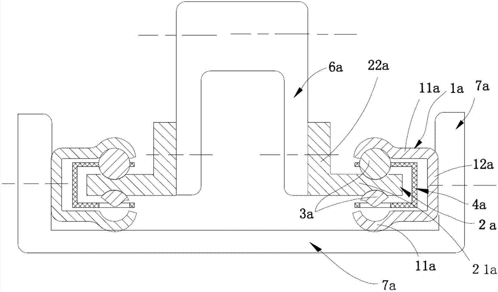
[0071] See Figure 2 to Figure 8 shown and emphatically see figure 2 , a group of four-row ball isosceles trapezoidal distributed thin ball slide rails B group, which is specially used as the ball slide rail in the bracket in the display lifting support frame (meaning that its application field is specific), it is characterized in that it includes:

[0072]An outer rail 1, including two adjacent and generally parallel plate-shaped raceway plates 11 (the two raceway plates 11 are generally parallel, and at the same time, an accommodation space is formed between them), the two raceway plates 11 together The longitudinal edges of the sides are mutually bent and extended to form a connected body part 12 (for example but not limited to this: that is, the outer rail 1 is generally approximately U-shaped when viewed from a cross section, and the connected body part 12 is equivalent to a U-shaped The two raceway plates 11 are equivalent to the U-shape to remove the remaining two sec...

Embodiment 2

[0088] The structure of this embodiment is basically the same as that of Embodiment 1, the difference is that:

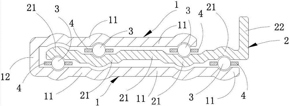
[0089] like Figure 9-15 As shown, there are four rows of balls and corresponding elongated ball racks 4, each row of balls is arranged along the longitudinal direction of the slide rail, each row of balls includes a plurality of balls 3 (for example, steel balls are used for balls 3), and each row of balls The balls 3 are all spaced apart and accommodated in the corresponding number of accommodations on the corresponding bead holders 4 (such as but not limited to, the structure of the bead holders 4 is a strip-shaped thin steel sheet with a row of accommodation holes corresponding to the number of balls 3 in the ball row). In the hole; from the cross-section of the slide rail, the connecting lines between the centers of the four rows of balls generally form a parallelogram (the centers of the four balls belonging to the four rows of balls are connected by a straigh...

Embodiment 3

[0094] This embodiment is basically the same as Embodiment 2, the difference is:

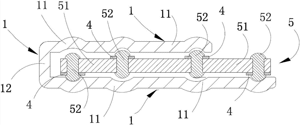
[0095] Four rows of balls and corresponding elongated ball racks 4, each row of balls are arranged along the longitudinal direction of the slide rail, each row of balls includes a plurality of balls 3 (such as steel balls 3), each row of balls 3 Be spaced, accommodated and held in the corresponding number of accommodation holes on the corresponding bead rack 4 (such as but not limited to, the structure of the bead rack 4 is a strip-shaped thin steel sheet with a row of accommodation holes corresponding to the number of balls 3 in the ball row); Viewed from the cross-section of the slide rail, one side of the raceway part 21 plate body and an adjacent raceway plate face jointly interfere with two rows of balls (two ball passages that jointly clamp and interfere with the row of balls are formed) ) and the line connecting the centers of the two rows of balls is defined as the first line connecting ...


PUM


Abstract

The invention provides a four-row ball slide rail and a knife type lifting bracket. The four-row ball slide rail comprises an outer rail, an inner rail, four rows of balls, and corresponding long ball frames; and the inner rail can linearly move back and forth corresponding to the outer rail through rolling and guidance of the four rows of balls. The four-row ball slide rail breaks through a structural mode of arranging two rows of balls in the slide rail thickness direction in an aligned manner habitually used by a slide rail in the prior art, so that a total thickness formula of the slide rail in the prior art is changed, that is, the total thickness of the two rows of balls is not obtained by directly adding the diameters of the balls anymore due to staggered arrangement of the four rows of balls, but is obviously lower than that of the total thickness of the four rows of balls, and the limit bottleneck on the whole slide rail thickness in the prior art is got rid of.

Description

technical field [0001] The invention relates to a ball slide rail used for lifting and lowering in the lifting support frame of a display (refers to liquid crystal type, including display, monitor, and flat panel display, the same below and referred to as display), in particular to a four-row ball slide rail. Background technique [0002] At present, the display screens of electronic products such as personal computers and televisions on the market are mainly liquid crystal displays. Liquid crystal displays are flat-panel displays. Location. In addition to the function of supporting the display, most of the display support frames must have the function of adjusting the height and position of the display, which requires the lifting module connected to the display in the display support frame to be able to lift. [0003] Because the ball-type slide rail has the advantages of smooth movement, stable structure, durability, small gap between moving parts, and small shaking, it ...

Claims


Application Information

Patent Timeline
Patent Type & Authority Applications(China)
IPC IPC(8): F16C29/04F16M11/04
CPCF16C29/048F16M11/046
Inventor 栾跃进
Owner TAIZHOU STRONKIN ELECTRONICS
Why Eureka
Try Eureka