Magnetorheological buffer

A magnetorheological buffer and outer cylinder technology, applied in the buffer field, can solve the problems of limited range of damping force, low magnetic field utilization, poor manufacturability, etc., and achieve the effects of compact layout, good structure matching and small structural changes

Inactive Publication Date: 2017-09-05
CHONGQING UNIV
View PDF10 Cites 10 Cited by
  • Summary
  • Abstract
  • Description
  • Claims
  • Application Information

AI Technical Summary

Problems solved by technology

The so-called built-in type is that the magnetic field generator is placed on the piston and moves up and down with the piston. The piston of this structure is an electromagnetic piston composed of a multi-stage magnetic circuit. The coil is led out of the shock absorber through the drilling of the piston rod. The range of the damping force produced is limited; the external structure is that the magnetic field generator is externally placed on the outer wall of the inner cylinder, such as the "magneto-rheological fluid shock absorber with an annular external magnetic field generator" disclosed in CN101319699A, And patent publication number CN103511546A discloses "A Magneto-rheological Fluid Shock Absorber for Vehicles Based on Multi-stage Circumferential Flow Mode"
Among them, CN101319699A is characterized in that the magneto-rheological fluid discharged by the piston movement all flows through the damping channel of the magnetic field generator, while CN103511546A adopts the volume compensation of the floating piston structure, and their common feature is that the magnetic field generator is distributed between the inner and outer cylinders, and Distributed along the axial direction, the structure is relatively complex, and installation is inconvenient

Method used


Image

  • Magnetorheological buffer
  • Magnetorheological buffer
  • Magnetorheological buffer

Examples


Embodiment Construction

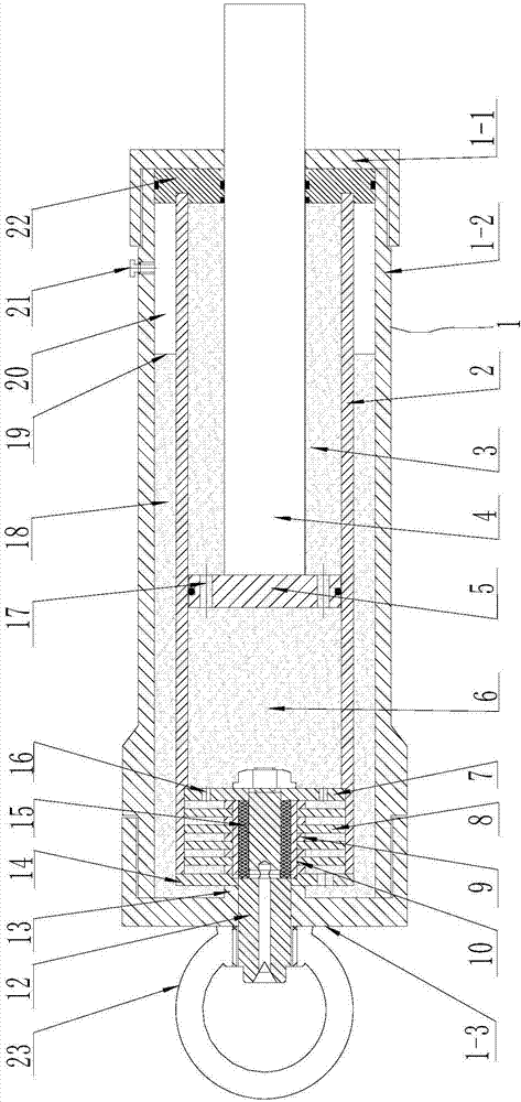
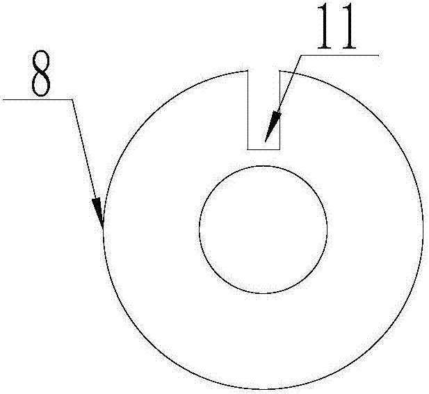
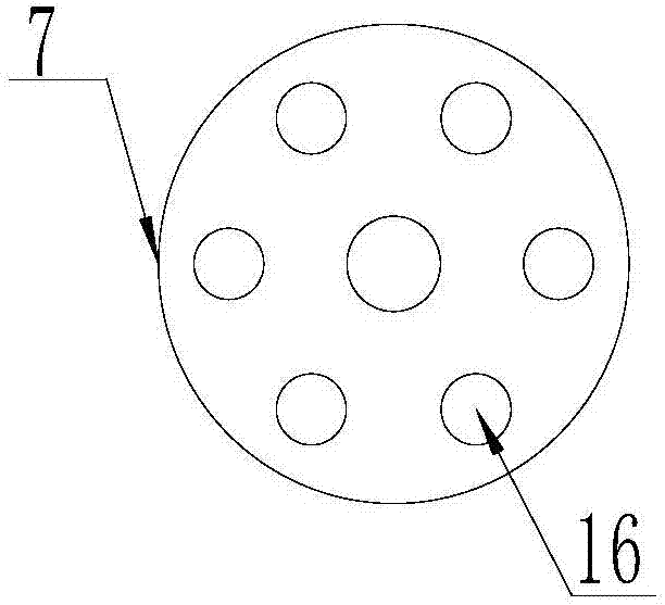
[0021] figure 1 Is a schematic diagram of the structure of the present invention, figure 2 It is a schematic diagram of the annular partition structure in the present invention, image 3 It is a schematic diagram of the upper positioning plate structure in the present invention, Figure 4 It is a schematic diagram of the structure of the lower positioning plate in the present invention, as shown in the figure: the magnetorheological damper of this embodiment includes an outer cylinder 1, an inner cylinder 2, a piston rod 4, and a piston 5, and the inner cylinder 2 is arranged at The outer cylinder tube 1 is in clearance fit with the inner wall of the outer cylinder tube 1, the piston 5 is placed in the inner cylinder tube 2, and the inner cavity of the inner cylinder tube 2 is divided into an upper working chamber 3, a lower working chamber 6, and the piston rod 4 and The piston 5 is fixedly connected and penetrates the inner cylinder 2 from the upper working chamber 3, and the...


PUM


Abstract

The invention discloses a magnetorheological buffer which comprises an outer cylinder barrel, an inner cylinder barrel, a piston and a piston rod. The inner cylinder barrel and the outer cylinder barrel are in clearance fit. The piston is arranged in the inner cylinder barrel and divides the inner cavity of the inner cylinder barrel into an upper working cavity and a lower working cavity. Inner cavities of the inner cylinder barrel and the outer cylinder barrel are filled with magnetorheological fluid. The inner cylinder barrel comprises a closed end and an open end. The open end communicates with the inner cavity of the outer cylinder barrel. The magnetorheological buffer further comprises a multistage circumferential damping channel arranged in the open end and a magnetic field generator used for adjusting damping force. The magnetorheological buffer can provide different damping forces under different vibrational excitation conditions, can be rapidly applied to a traditional damper structure, is high in extension capacity and rapid in response speed and has good stability and reliability; when the magnetorheological buffer is used, since the open end of the inner cylinder barrel is located at the bottom, the multistage circumferential damping channel of the buffer achieves the effect of a throttle valve, and according to vibrational excitation, under the effect of a controller, different excitation currents are applied, and therefore the damping force is controllable.

Description

Technical field [0001] The present invention relates to the field of buffer technology, in particular to a magnetorheological buffer that can be used in vehicles, aerospace, heavy machinery and weapons. Background technique [0002] Buffers play a vital role in automobile suspension, aircraft landing gear, artillery recoil devices, elevator systems, sliding seat systems and other fields. Shock absorbers based on magnetorheological fluids have been a research hotspot in recent years, and they are common The magnetorheological fluid shock absorber has different structures. As far as the magnetic field generator assembly is concerned, there are two structures: built-in and external. The so-called built-in type is that the magnetic field generator is placed on the piston and moves up and down with the piston. The piston of this structure is an electromagnetic piston composed of a multi-stage magnetic circuit. The coil is led out of the shock absorber through the piston rod borehole, ...

Claims


Application Information

Patent Timeline
Patent Type & Authority Applications(China)
IPC IPC(8): F16F9/06F16F9/348F16F9/53
CPCF16F9/062F16F9/067F16F9/3484F16F9/3487F16F9/535
Inventor 张红辉肖允恒杨涛
Owner CHONGQING UNIV
Why Eureka
Try Eureka