Voltage source type adjusting device and control method thereof

An adjustment device and voltage source technology, which is applied in the direction of AC network voltage adjustment, AC network load balancing, etc., can solve problems such as slow closing speed, device failure, and load loss of power, so as to ensure normal operation and improve reliability. Effect

Inactive Publication Date: 2017-09-05
NR ELECTRIC CO LTD +1
View PDF7 Cites 2 Cited by
  • Summary
  • Abstract
  • Description
  • Claims
  • Application Information

AI Technical Summary

Problems solved by technology

Patent CN103457283B introduces the typical composition and working principle of this device. Due to the limitation of voltage and current stress of power electronic devices, the capacity of a single inverter of a voltage source adjustment device is limited, and the load to be compensated has a high voltage and a large current. Therefore, it is necessary to consider how to make the inverter easy to expand
[0003] Because the device is connected in series between the power grid and the load, the reliability of the device itself is very important, and it is difficult to guarantee reliability only by relying on solid-state switches. Patent CN103457283B also includes a mechanical circuit breaker, but the closing speed of the mechanical circuit breaker is very fast. Slow, when the solid-state switch fails, it takes tens of milliseconds to close the mechanical circuit breaker at this time, and some sensitive loads will stop working within 5ms, especially for high-voltage and large-capacity loads. It will contain a large number of power semiconductor devices. Once a single power semiconductor device fails, it will cause the device to fail, or even cause the load to lose power. In practical applications, it is necessary to consider the reliability of the voltage source regulator.

Method used


Image

  • Voltage source type adjusting device and control method thereof
  • Voltage source type adjusting device and control method thereof
  • Voltage source type adjusting device and control method thereof

Examples


Embodiment Construction

[0036] The technical solutions and beneficial effects of the present invention will be described in detail below with reference to the accompanying drawings.

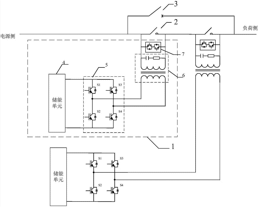
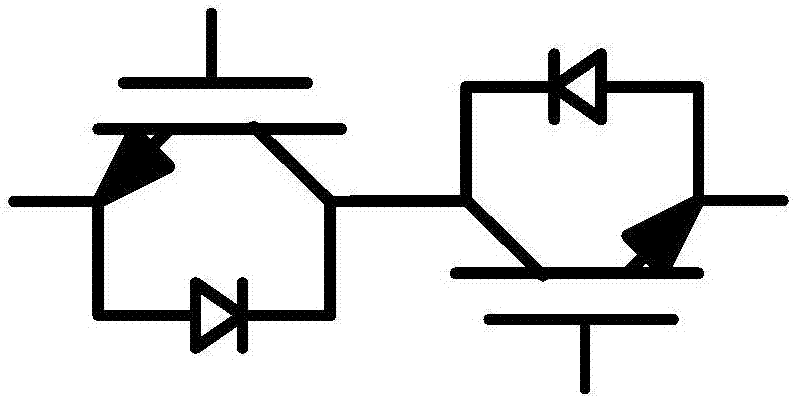
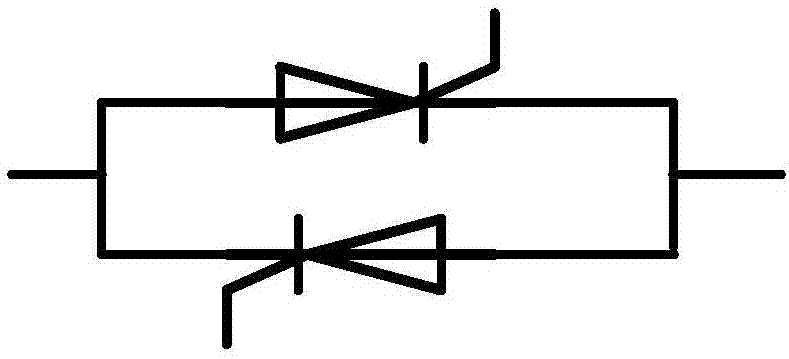
[0037] like figure 1 As shown, the present invention provides a voltage source type regulating device, comprising a circuit breaker 3, at least two sets of compensation units 1, and a fast mechanical switch 2 with the same number as the compensation unit, the fast mechanical switch 2 and the compensation unit 1 one by one Corresponding to the parallel connection, all the compensation units 1 are connected in series and then connected in parallel with the circuit breaker 3, one end of the circuit breaker 3 is connected to the power supply side, and the other end is connected to the load side; wherein, the compensation unit 1 includes an energy storage unit 4 and a power conversion unit 5. , a filter isolation unit 6, a solid state switch unit 7, the power conversion unit 5 is composed of a power semiconductor device, and...


PUM


Abstract

The invention discloses a voltage source type adjusting device. The voltage source type adjusting device comprises a circuit breaker, at least two compensation units and fast mechanical switches, wherein the number of the fast mechanical switches is equal to that of the compensation units. The fast mechanical switches are correspondingly connected with the compensation units in parallel, all the compensation units are connected in series and then connected with the circuit breaker in parallel, one end of the circuit breaker is connected with the power source side, and the other end of the circuit breaker is connected with the load side. The compensation unit comprises an energy storage unit, a power conversion unit, a filtering isolating unit and a solid state switch unit, the power conversion unit is formed by a power semiconductor device and used for converting direct currents into alternating currents, the direct current end of the power conversion unit is connected with the energy storage unit, the alternating current end is connected with the primary side of the filtering isolating unit, and the secondary side of the filtering isolating unit is connected with the solid state switch unit; the solid state switch unit comprises a power semiconductor device. The voltage source type adjusting device is convenient to expand and is high in reliability. The invention further discloses a control method of the voltage source type adjusting device.

Description

technical field [0001] The invention relates to a power electronic converter, in particular to a voltage source type regulating device and a control method thereof. Background technique [0002] The voltage source type regulating device is connected in series between the power supply and the load. When it is normal, the device is in the bypass standby state. When the power supply voltage is abnormal, it can be put into operation immediately, and the compensation voltage can be output to maintain the load voltage in the normal range. In the case of short-term abnormal voltage of the power grid, ensure the continuous operation of the load and avoid abnormal power outages. Patent CN103457283B introduces the typical composition and working principle of the device. Due to the limitation of voltage and current stress of power electronic devices, the capacity of a single inverter of the voltage source regulating device is limited, and the load of the compensation object has high vo...

Claims


Application Information

Patent Timeline
Patent Type & Authority Applications(China)
IPC IPC(8): H02J3/12H02J3/28
CPCH02J3/12H02J3/28
Inventor 刘洪德连建阳王宇谢晔源祁琦刘为群
Owner NR ELECTRIC CO LTD
Why Eureka
Try Eureka