Tapestry brick bonding strength sample site automatic cutting device

An automatic cutting device and bonding strength technology, which is used in the preparation and sampling of measuring devices, samples for testing, etc., can solve problems such as low efficiency, visual errors, and high operating level requirements, and achieve improved cutting quality and efficiency. Automate the effect

Active Publication Date: 2017-09-08
山东金谷信息技术有限公司
View PDF8 Cites 0 Cited by
  • Summary
  • Abstract
  • Description
  • Claims
  • Application Information

AI Technical Summary

Problems solved by technology

[0002] Before the completion of the construction project, it is necessary to carry out on-site inspection of the bonding strength of the facing brick. During the inspection, a standard test piece with a length of 95 mm, a width of 45 mm or a length of 45 mm and a width of 45 mm should be cut on the wall of the facing brick to reach the concrete wall or masonry. The sample is used for the bonding strength test. The quality of the sample after cutting directly affects the result of the bonding strength test. At present, the cutting sample is manually cut on the wall with a hand-held electric saw, which requires a high level of operation and is very difficult. Large, even people with a good level often have the situation that the adjacent cutting surfaces are not perpendicular to the wall finish. Sometimes it is necessary to cut on the high-altitude wall. When cutting on the wall, the saw blade will generate vibration, noise and dust during the process of cutting into the wall and moving the chainsaw, causing trembling of hands, visual errors, etc., resulting in the quality of the sample after cutting not meeting the requirements, such as inaccurate size and shape deviation , loose bonding layer, etc., cannot effectively guarantee the quality of the sample, the working environment is harsh, and the efficiency is not high

Method used


Image

  • Tapestry brick bonding strength sample site automatic cutting device
  • Tapestry brick bonding strength sample site automatic cutting device
  • Tapestry brick bonding strength sample site automatic cutting device

Examples


Embodiment Construction

[0017] In order to make the purpose, technical solutions and advantages of the embodiments of the present invention clearer, the technical solutions in the embodiments of the present invention will be clearly and completely described below in conjunction with the drawings in the embodiments of the present invention. Obviously, the described embodiments It is a part of embodiments of the present invention, but not all embodiments. Based on the embodiments of the present invention, all other embodiments obtained by those skilled in the art without creative efforts fall within the protection scope of the present invention.

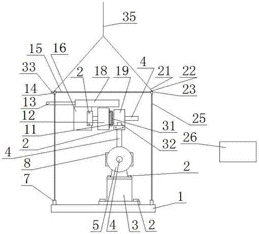
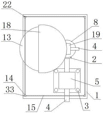
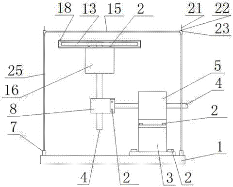
[0018] The invention provides an on-site automatic cutting device for the adhesive strength sample of facing tiles, which mainly includes four parts: a cutting saw part, a moving part, a hanging cage part and a PLC controller. The structures and functions of these four parts are described in detail below. introduce.

[0019] Cutting saw part comprises cuttin...


PUM


Abstract

The invention belongs to the technical field of building material product detection, and particularly relates to a tapestry brick bonding strength sample cutting device. The tapestry brick bonding strength sample cutting device comprises a cutting saw. The cutting saw is fixedly connected with the left end of a telescopic shaft of a horizontal telescopic shaft motor A through a bolt. A coupling is fixed to the right end of a shell of the horizontal telescopic shaft motor A. The right end of the coupling is connected with a pressure ring sensor. The pressure ring sensor is mounted at the end of a hollow shaft motor. The lower end of the hollow shaft motor and a vertical telescopic shaft motor are fixedly connected together. The vertical telescopic shaft motor and the other horizontal telescopic shaft motor B are fixedly connected together. The horizontal telescopic shaft motor B is fixed to a support. The support is fixed to a bottom disc of a cage. The cutting saw, the horizontal telescopic shaft motor A, the pressure ring sensor, the hollow shaft motor, the vertical telescopic shaft motor and the horizontal telescopic shaft motor B are all connected with a PLC.

Description

technical field [0001] The invention belongs to the technical field of building material product testing, and in particular relates to a cutting device for a veneer brick bonding strength sample. Background technique [0002] Before the completion of the construction project, it is necessary to carry out on-site inspection of the bonding strength of the facing brick. During the inspection, a standard test piece with a length of 95 mm, a width of 45 mm or a length of 45 mm and a width of 45 mm should be cut on the wall of the facing brick to reach the concrete wall or masonry. The sample is used for the bonding strength test. The quality of the sample after cutting directly affects the result of the bonding strength test. At present, the cutting sample is manually cut on the wall with a hand-held electric saw, which requires a high level of operation and is very difficult. Large, even people with a good level often have the situation that the adjacent cutting surfaces are n...

Claims


Application Information

Patent Timeline
Patent Type & Authority Applications(China)
IPC IPC(8): B28D1/04B28D7/00G01N1/28
CPCB28D1/04B28D7/00B28D7/005G01N1/286G01N2001/2873
Inventor 闫靖媛
Owner 山东金谷信息技术有限公司
Why Eureka
Try Eureka