Magnetron sputtering glancing angle deposition coating device

A technology of inclined deposition and coating device, applied in sputtering coating, ion implantation coating, vacuum evaporation coating and other directions, can solve the problems of prolonging the experimental period, affecting the experimental efficiency, time-consuming and labor-intensive, etc., to increase the experimental possibility. The effect of changing parameters, avoiding vacuum operation and improving work efficiency

Inactive Publication Date: 2017-09-08
UNIV OF ELECTRONIC SCI & TECH OF CHINA
View PDF9 Cites 6 Cited by
  • Summary
  • Abstract
  • Description
  • Claims
  • Application Information

AI Technical Summary

Problems solved by technology

However, there are also some disadvantages in the preparation of nanostructures by the template method: organic compound templates need to be removed with organic solvents, which will destroy the structure of nanomaterials to

Method used


Image

  • Magnetron sputtering glancing angle deposition coating device
  • Magnetron sputtering glancing angle deposition coating device

Examples


Embodiment 1

[0024] During multi-target co-sputtering experiments:

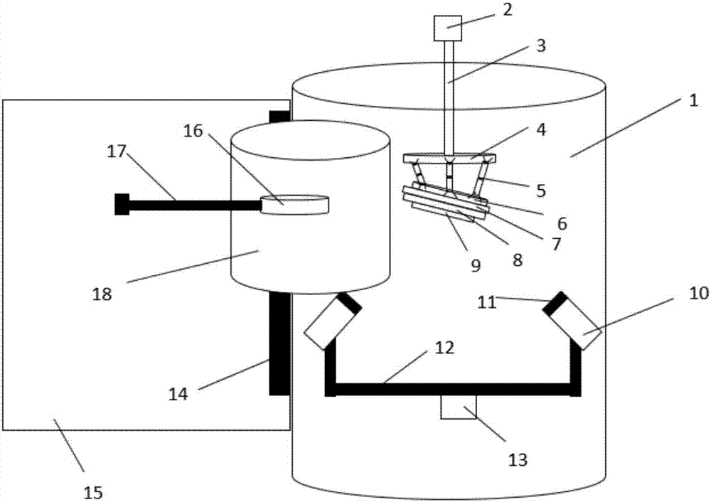
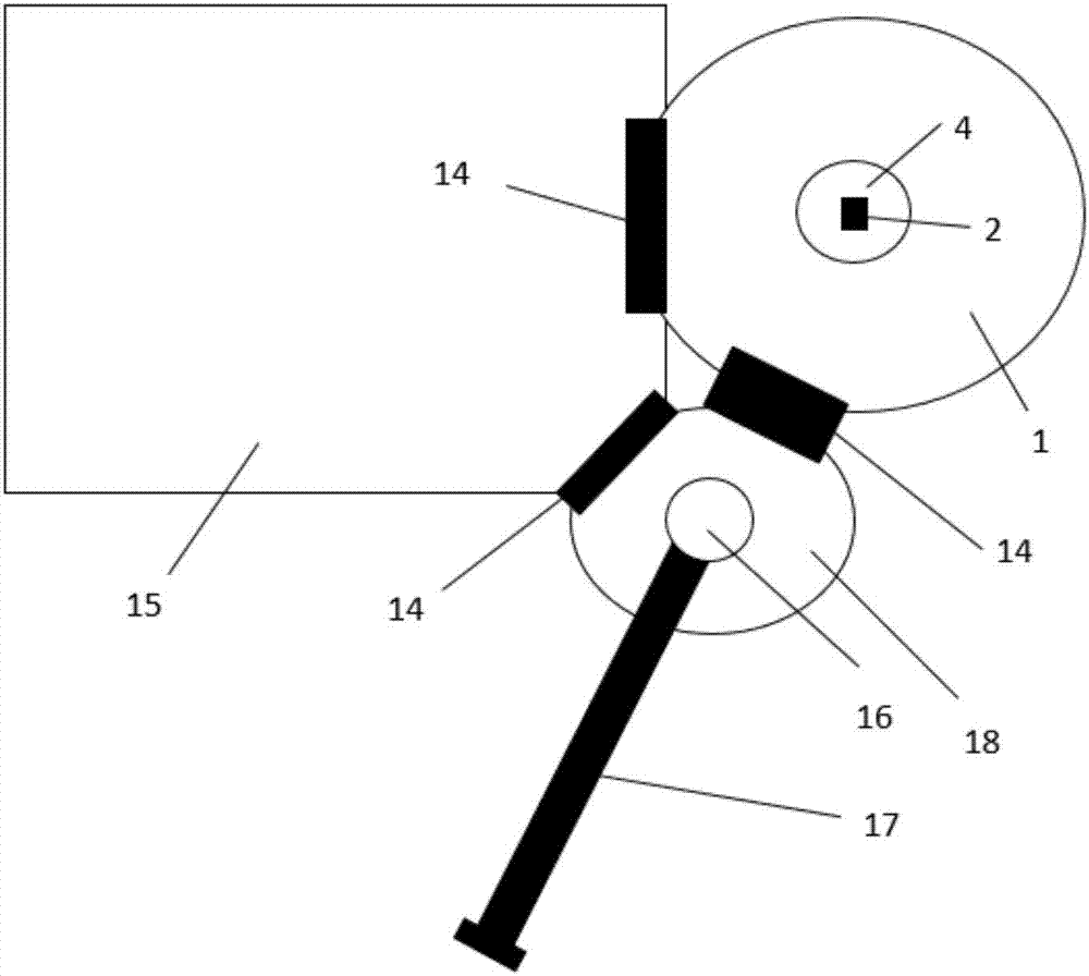
[0025] 1. Put the target material 11 into the glove box 15, open the chamber door 14 between the glove box 15 and the sputtering chamber 1, and install the target material 11 on the top of the target gun 10;

[0026] 2. Adjust and fix the position and angle of the target gun 10;

[0027] 3. Put the substrate to be plated 9 into the glove box 15, open the chamber door 14 between the glove box 15 and the transition chamber 18, and place the substrate to be plated on the transfer substrate frame 16 in the transition chamber 18;

[0028] 4. Open the chamber door 14 between the transition chamber 18 and the sputtering chamber 1, and transfer the substrate 9 to the sputtering chamber 1 through the magnetic transfer device 17;

[0029] 5. Take off the substrate 9 to be plated on the transfer substrate rack 16, and install and fix it on the substrate rack 8;

[0030] 6. Close the chamber door 14 between the transition chamber 1...

Embodiment 2

[0040] During grazing incidence experiments:

[0041] 1. Put the target material 11 into the glove box 15, open the chamber door 14 between the glove box 15 and the sputtering chamber 1, and install the target material 11 on the top of the target gun 10;

[0042] 2. Adjust and fix the position and angle of the target gun 10;

[0043] 3. Put the substrate to be plated 9 into the glove box 15, open the chamber door 14 between the glove box 15 and the transition chamber 18, and place the substrate to be plated on the transfer substrate frame 16 in the transition chamber 18;

[0044] 4. Open the transition chamber 18 and the chamber door 14 of the sputtering chamber 1, and transfer the substrate 9 to the sputtering chamber 1 through the magnetic transfer device 17;

[0045] 5. Take off the substrate 9 to be plated on the transfer substrate rack 16, and install and fix it on the substrate rack 8;

[0046]6. Close the chamber door 14 between the transition chamber 18 and the sputt...


PUM


Abstract

The invention relates to the technical field of vacuum film-coating, and specifically relates to a magnetron sputtering glancing angle deposition coating device. The magnetron sputtering glancing angle deposition coating device comprises a sputtering chamber, a chamber door, a glove box and a transition chamber. According to the magnetron sputtering glancing angle deposition coating device, continuous changing of angles of a to-be-coated substrate is achieved through a plurality of extensible supports which can be adjusted independently; by utilizing configuration of the glove box, through mutual connecting between the sputtering box, the glove box and the transition box, the working atmosphere of the magnetron sputtering device keeps stable in the process of substrate and target material changing, the vacuum degree of the sputtering chamber is not damaged, once more vacuumizing operation is avoided, and the working efficiency is enhanced; magnetron sputtering film-coating in a horizontal state and at continuous inclined angles can be completed; the to-be-coated substrate is changed without damaging a vacuum condition, so that promotion of the efficiency is achieved; the to-be-substrate can be heated, so that the variable parameters of an experiment are added; and target material changing under an inert gas condition is achieved through an externally connected equipment, namely the glove box.

Description

technical field [0001] The invention relates to the technical field of vacuum coating, in particular to a magnetron sputtering oblique deposition coating device. Background technique [0002] Nanopillars are a highly ordered nanoarray structure. At present, the methods for preparing nanopillars mainly include: nanoimprint technology, (extreme) extreme ultraviolet lithography, electron / ion beam lithography, template method and other means. [0003] Compared with other methods, the nanostructure prepared by the template method has considerable flexibility, simple experimental equipment, mild operating conditions, and the ability to precisely control the size, shape and structure of nanomaterials, so it has attracted widespread attention. However, the preparation of nanostructures by the template method also has some disadvantages: organic compound templates need to be removed with organic solvents, which will destroy the structure of nanomaterials to a certain extent; some or...

Claims


Application Information

Patent Timeline
IPC IPC(8): C23C14/35
CPCC23C14/35C23C14/225
Inventor 向勇刘雯闫宗楷彭志蒋赵联吴露
Owner UNIV OF ELECTRONIC SCI & TECH OF CHINA
Why Eureka
Try Eureka