Elastic extrusion-type tightening mechanism for special paper coater
A technology of tensioning mechanism and coating machine, which is applied in the direction of papermaking, textile and papermaking, pulp raw material addition process, etc. It can solve the problems of paper arching and affecting the quality of coating, so as to prevent excessive friction and ensure the quality of transmission Effect
- Summary
- Abstract
- Description
- Claims
- Application Information
AI Technical Summary
Problems solved by technology
Method used
Image

Examples
Embodiment Construction
[0019] Referring to the accompanying drawings, through the description of the embodiments, the specific embodiments of the present invention include the shape, structure, mutual position and connection relationship of each part, the function and working principle of each part, and the manufacturing process of the various components involved. And the method of operation and use, etc., are described in further detail to help those skilled in the art have a more complete, accurate and in-depth understanding of the inventive concepts and technical solutions of the present invention.
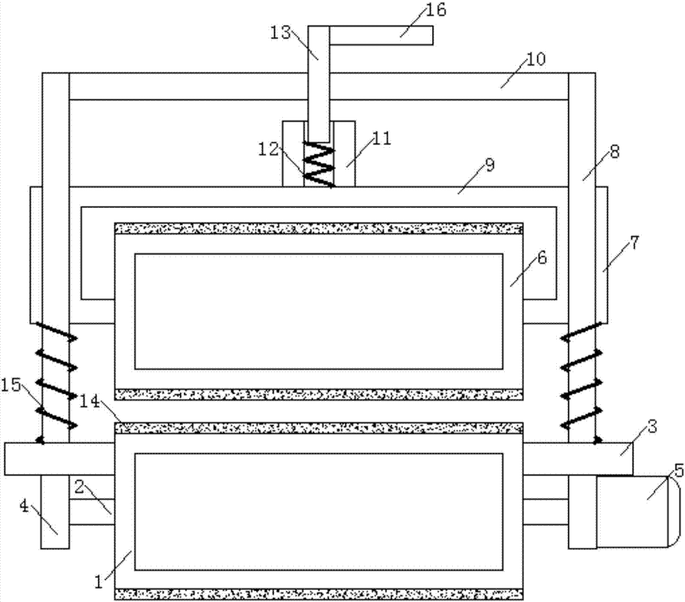
[0020] An elastic extrusion tensioning mechanism of a special paper coating machine, comprising a driving roller 1, the middle of the left and right ends of the driving roller 1 is provided with a lower rotating shaft 2, and the driving roller 1 is located under the working table 3 of the coating machine On the other side, there is a receiving groove corresponding to the upper end of the driving rolle...
PUM
 Abstract
Description
Claims
Application Information
 - R&D
- Intellectual Property
- Life Sciences
- Materials
- Tech Scout
- Unparalleled Data Quality
- Higher Quality Content
- 60% Fewer Hallucinations
Browse by: Latest US Patents, China's latest patents, Technical Efficacy Thesaurus, Application Domain, Technology Topic, Popular Technical Reports.
© 2025 PatSnap. All rights reserved.Legal|Privacy policy|Modern Slavery Act Transparency Statement|Sitemap|About US| Contact US: help@patsnap.com