Structure and Construction Method of Penetrating Abutment Slab

A bridge abutment and slab technology, which is applied to bridges, bridge construction, bridge parts, etc., can solve problems such as increasing the consolidation and settlement of corbel soil, increasing the void volume of slabs, and easy fracture of slabs, etc. Achieve the effects of improving bad conditions, simple construction, and solving water seepage problems

Active Publication Date: 2019-08-27
云南交投集团公路建设有限公司 +4
View PDF6 Cites 0 Cited by
  • Summary
  • Abstract
  • Description
  • Claims
  • Application Information

AI Technical Summary

Problems solved by technology

[0003] The main disadvantage of this slab-lapping technology is that due to the existence of the platform back corbel, the soil near and below the corbel cannot be effectively compacted during the compaction process of the subgrade by the compactor, resulting in this Part of the soil subsides under the action of its own weight and consolidation, resulting in an increase in the void volume of the slab and further aggravating the fracture of the slab; secondly, the rainwater on the road surface in the transition section is easy to pass through the gap between the end of the slab and the back of the platform. Expansion joints in between penetrate into the soil, increasing the consolidation and settlement of the soil near the corbel, increasing the voidage of the slab, and making the slab more likely to break

Method used


Image

  • Structure and Construction Method of Penetrating Abutment Slab
  • Structure and Construction Method of Penetrating Abutment Slab

Examples


Embodiment Construction

[0028] The present invention will be further described in detail below in conjunction with the accompanying drawings, so that those skilled in the art can implement it with reference to the description.

[0029] It should be understood that terms such as "having", "comprising" and "including" as used herein do not entail the presence or addition of one or more other elements or combinations thereof.

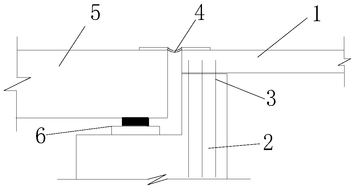
[0030] Such as figure 1 As shown, the present invention provides a structure of through abutment 2 buttress 1, comprising:

[0031] Abutment 2;

[0032] One end of the butt plate 1 is anchored on the abutment 2 by extending out the steel bar on the top surface of the abutment 2, and the other end is placed on the roadbed.

[0033] In one of the embodiments of the present invention, preferably, in the structure of the through abutment 2 butt 1 , one end of the butt 1 is fixed to the abutment 2 by a steel bar 3 protruding from the top surface of the abutment 2 superior.

[0034...


PUM


Abstract

The invention discloses a connective bridging slab structure comprising a bridge abutment and a butt slab, wherein one end of the butt slab is fixedly anchored with the bridge abutment through steel bars extending outside the bridge abutment top, and the other end is jointed on the roadbed. The invention also discloses a connective bridging slab structure construction method comprising the following steps: 1, determining the areas of the steel bars extending outside the bridge abutment top: assuming the butt slab is rigid and the most outside steel bars extending outside the bridge abutment top reach yielding, actual measuring modulus deformation of the compressed roadbed soil body, determining the soil body maximum strain, and obtaining the areas of the steel bars extending outside the bridge abutment top through moment balance and obtaining the bridge abutment top distribution areas; 3, casting the bridge abutment and the butt slab, and connecting the butt slab with the bridge abutment: casting the bridge abutment, placing a butt slab steel bar net frame on the bridge abutment top when the bridge abutment concrete reaches the required intensity, welding or binding the steel bars extending outside the bridge abutment top with the butt slab steel bar net frame, fixing the butt slab steel bar net frame on the bridge abutment top, connecting the butt slab with the bridge abutment top, and casting butt slab concrete.

Description

technical field [0001] The invention belongs to the technical field of highway and bridge engineering, and relates to a through-type abutment lapping plate structure and a construction method thereof. Background technique [0002] Nowadays, the slabs in the transitional sections of bridges and roads are generally firstly reinforced according to the construction drawings, and after the concrete is poured into shape, one end of the slab is placed on the corbel on the back of the platform, and a telescopic structure is set between the end of the slab and the back of the platform. seam while placing the other end of the board on the compacted roadbed. [0003] The main disadvantage of this slab-lapping technology is that due to the existence of the platform back corbel, the soil near and below the corbel cannot be effectively compacted during the compaction process of the subgrade by the compactor, resulting in this Part of the soil subsides under the action of its own weight a...

Claims


Application Information

Patent Timeline
Patent Type & Authority Patents(China)
IPC IPC(8): E01D19/00E01D21/00
Inventor 张国辉宋桂锋柯鉴王晓东关凤林茶增云李建龙王云龙赵尚传张一张志韬
Owner 云南交投集团公路建设有限公司
Why Eureka
Try Eureka