Well structure design and method for exploiting geothermal energy and gas hydrate reservoir at the same time of water injection

A hydrate and geothermal energy technology, which can be used in heating devices, other non-combustion heat generation, and production of fluids, etc., can solve the problems of not proposing natural gas hydrate reservoirs, restricting the development and utilization of natural gas hydrate reservoirs, etc., achieving convenient operation, Simple and economical equipment

Active Publication Date: 2017-09-08
CHINA UNIV OF PETROLEUM (EAST CHINA)
View PDF6 Cites 10 Cited by
  • Summary
  • Abstract
  • Description
  • Claims
  • Application Information

AI Technical Summary

Problems solved by technology

However, there is no method to develop natural gas hydrate reservoirs using geothermal energy, which greatly restricts the development and utilization of natural gas hydrate reservoirs.

Method used


Image

  • Well structure design and method for exploiting geothermal energy and gas hydrate reservoir at the same time of water injection
  • Well structure design and method for exploiting geothermal energy and gas hydrate reservoir at the same time of water injection

Examples


Embodiment Construction

[0017] The present invention will be further described below in conjunction with the accompanying drawings, but the implementation scope of the present invention is not limited.

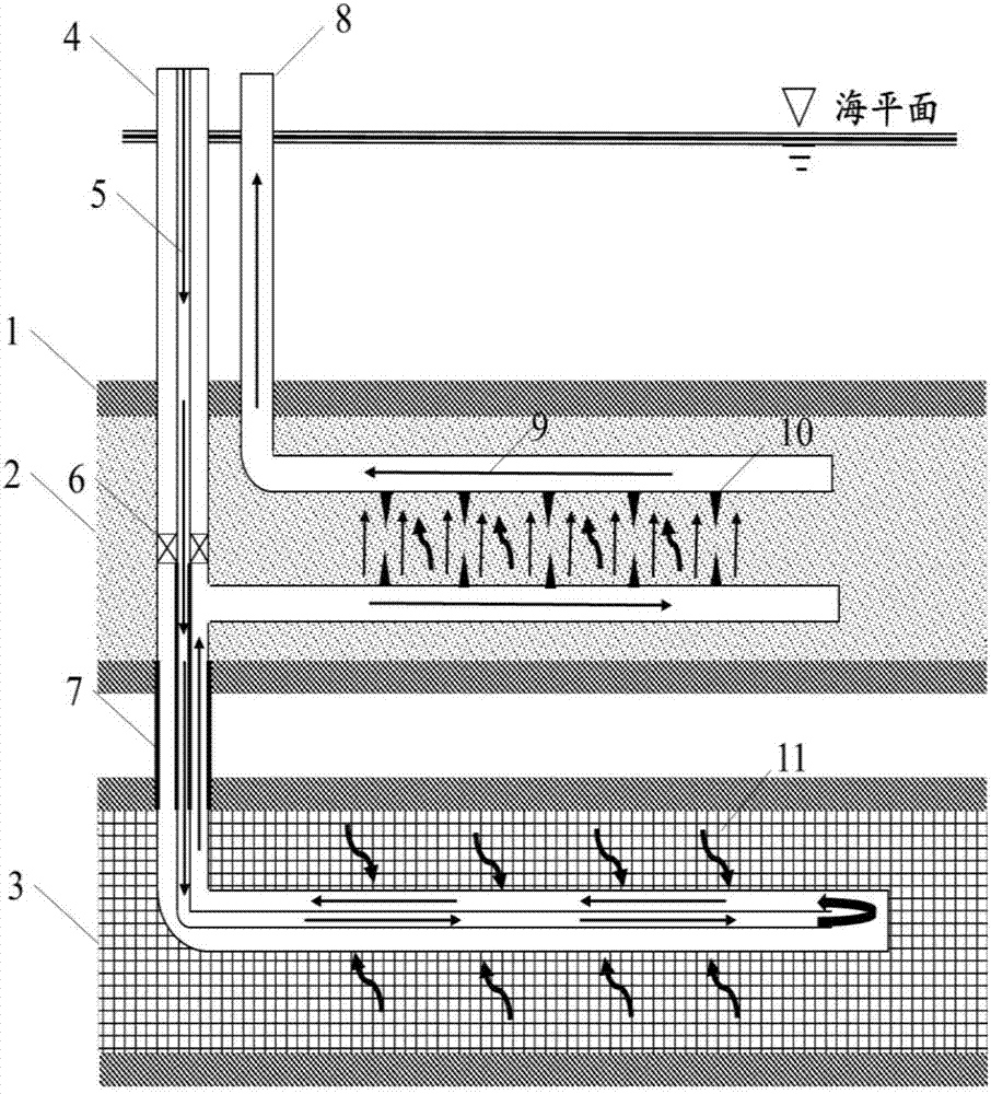
[0018] (1) if figure 1 As shown, according to the geological data of the hydrate reservoir 2, the area with cap rock 1 at the top and geothermal layer 3 at the bottom is selected for construction work, and the temperature of geothermal layer 3 is 120°C;

[0019] (2) if figure 1 As shown, a well group system consisting of a dual branch injection well and a horizontal production well 8 is drilled in the construction area, where the dual branch injection well includes a vertical wellbore extending from sea level to the geothermal layer 3, located at The first branch wellbore with a length of 700m at the position and the geothermal layer 3 distance from the top The second branch wellbore with a length of 700m at the position, the horizontal production well 8 is located at the top of the hydrate reser...


PUM


Abstract

The invention discloses a well structure design and method for exploiting geothermal energy and gas hydrate reservoir at the same time of water injection. The design mainly comprises a dual branch injection well and a horizontal producing well, wherein cold fluid is injected into the dual branch injection well, heated by a geothermal layer and returned to the gas hydrate reservoir; the self-carrying heat is transmitted to hydrate, and the hydrate dissociation is promoted. The method comprises the steps that a well group system which is composed of the dual branch injection well and the horizontal producing well is built on the sea level, wherein the dual branch injection well comprises a vertical mineshaft which extends from the sea level to the geothermal layer, a first branch mineshaft which is located on the gas hydrate reservoir and a second branch mineshaft which is located on the geothermal layer; the cold fluid is injected into a wellhead oil tube of the dual branch injection well, the cold fluid enters an oil sleeve annulus at the tail end of the second branch mineshaft and is subjected to heat exchange with the geothermal layer, after the heated fluid enters the gas hydrate reservoir, the heat is transmitted to the gas hydrate reservoir, the hydrate dissociation is caused, and mixed fluid which is composed of natural gas and injection fluid generated by the dissociation passes through a hydraulic power fracturing fracture under the gravity and pressure effect and is exploited by the horizontal producing well. According to the well structure design and method, the geothermal energy provides energy for the hydrate dissociation, the shortages such as low heat utilization efficiency and high exploiting cost in a traditional thermal excitation exploiting method are overcome, the device is simple, the operation is convenient, the economy is high, and the well structure design and method can provide guidance for reasonable exploiting of the gas hydrate reservoir.

Description

technical field [0001] The invention relates to a method for exploiting natural gas hydrate, in particular to a well structure design and method for establishing a well group system composed of a double-branch injection well and a horizontal production well and using geothermal energy to exploit natural gas hydrate reservoirs. Background technique [0002] With the massive consumption of oil and gas resources, mankind will face a serious resource crisis in the late 21st century. As clean energy with abundant reserves, geothermal energy and natural gas hydrate have attracted extensive attention of scientists from all over the world. [0003] At present, the mining methods of marine natural gas hydrate mainly include thermal stimulation mining method, depressurization mining method, chemical agent injection method and solid mining method. However, the above mining methods have their own limitations. For example, the thermal stimulation mining method has large heat loss and lo...

Claims


Application Information

Patent Timeline
Patent Type & Authority Applications(China)
IPC IPC(8): E21B43/01E21B43/24E21B43/20E21B43/30E21B43/26F24J3/08
CPCE21B43/01E21B43/20E21B43/24E21B43/2405E21B43/26E21B43/305E21B41/0099
Inventor 刘永革侯健杜庆军张广福赵海峰陆努刘晓宇刘璟垚
Owner CHINA UNIV OF PETROLEUM (EAST CHINA)
Why Eureka
Try Eureka