
Method and apparatus for obtaining cyclic temperature field

A technology of circulating temperature and differential equations, which is applied in special data processing applications, instruments, electrical digital data processing, etc. It can solve the problems of not considering the influence of seawater convection, different calculation methods, and inability to completely calculate the transient temperature distribution of the wellbore.

Active Publication Date: 2017-09-08
CHINA NAT OFFSHORE OIL CORP +2
View PDF4 Cites 9 Cited by
  • Summary
  • Abstract
  • Description
  • Claims
  • Application Information

AI Technical Summary

Problems solved by technology

[0013] Using the above calculation formula, the wellbore circulation temperature can be obtained based on the numerical iteration method; although the above method is concise, the above method is only suitable for surface drilling, not for deep water drilling; and the considerations of drilling cycle and non-drilling cycle in numerical calculation Different, different mathematical methods need to be used to calculate separately; In deep water areas, in order to increase the mud carrying capacity, pressurized flow is usually added to the annulus at the seabed, so the fluid flow in the entire annulus area is uneven , this point is not considered in the above calculation formula, resulting in a large deviation in the prediction of the annular space temperature
In addition, seawater convection rather than heat conduction occurs on the outside of the riser or pipe string in the deep water area. The above calculation formula does not consider the influence of seawater convection, and there is an error in the transient temperature distribution obtained during deepwater drilling.
[0014] The general calculation method disclosed above requires numerical iteration after the model is discretized. However, the factors involved in the drilling and non-drilling processes are different, and the calculation methods are also different. At present, there is no public general algorithm, and it is impossible to completely calculate Transient temperature distribution of wellbore during non-drilling

Method used


Image

  • Method and apparatus for obtaining cyclic temperature field
  • Method and apparatus for obtaining cyclic temperature field
  • Method and apparatus for obtaining cyclic temperature field

Examples


Embodiment Construction

[0140] In order to make the purpose, technical solution and advantages of the present invention more clear, the embodiments of the present invention will be described in detail below in conjunction with the accompanying drawings. It should be noted that, in the case of no conflict, the embodiments in the present application and the features in the embodiments can be combined arbitrarily with each other.

[0141] The steps shown in the flowcharts of the figures may be performed in a computer system, such as a set of computer-executable instructions. Also, although a logical order is shown in the flowcharts, in some cases the steps shown or described may be performed in an order different from that shown or described herein.

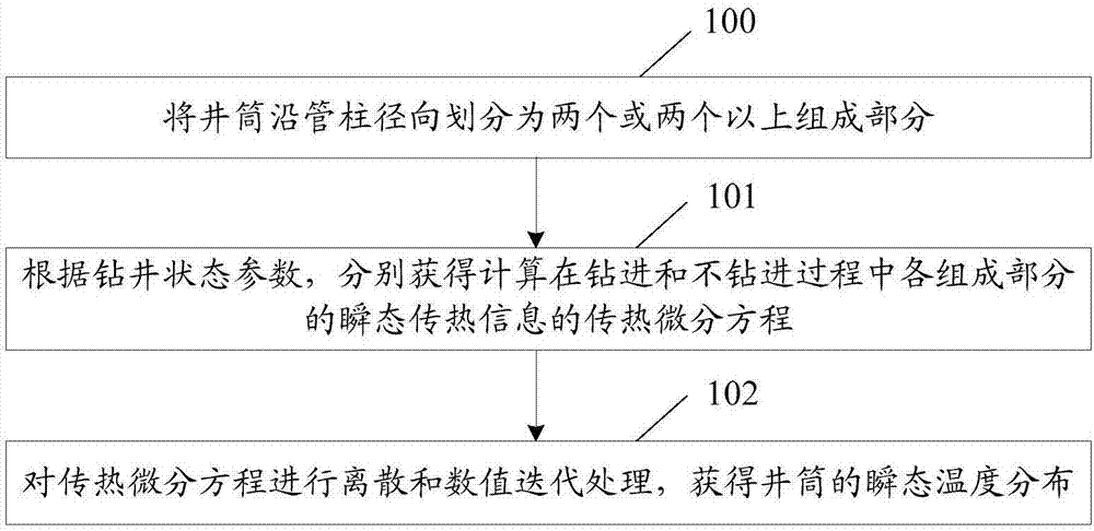
[0142] figure 1 A flowchart of a method for obtaining a cyclic temperature field according to an embodiment of the present invention, such as figure 1 shown, including:

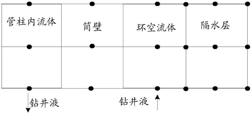
[0143] Step 100, dividing the wellbore into two or more components along the pipe ...


PUM


Abstract

The invention discloses a method and an apparatus for obtaining a cyclic temperature field. The method comprises the steps of dividing a shaft into two or more component parts in a radial direction of a pipe column; according to well drilling state parameters, obtaining a heat transfer differential equation for calculating transient heat transfer information of the component parts in drilling and non-drilling processes; and performing discrete and numerical iteration processing on the heat transfer differential equation to obtain transient temperature distribution of the shaft. According to the method and the apparatus, the cyclic temperature field is calculated according to the well drilling state parameters, so that the cyclic temperature field can be obtained in the drilling and non-drilling processes, and the working efficiency of obtaining the cyclic temperature field is improved.

Description

technical field [0001] This article involves but is not limited to oil drilling technology, especially a method and device for obtaining a circulating temperature field. Background technique [0002] Wellbore circulation temperature has a great influence on drilling and cementing engineering. It is not only related to the success or failure of cementing operation and the quality of cementing, but also related to the pressure balance in the well, the stability of the well wall, the selection of the working fluid system in the well, casing and drilling. It is related to column strength design and other aspects. Therefore, it is of great significance to accurately determine the distribution of wellbore circulating temperature and its changing law for the design of cement slurry system, well control and safe and rapid drilling. [0003] Since the 1960s, many foreign scholars have conducted research on wellbore circulating temperature, and established different theoretical model...

Claims


Application Information

Patent Timeline
IPC IPC(8): G06F19/00
CPCG16Z99/00
Inventor 刘文成赵丹汇赵琥李旭罗宇维宋茂林郭朝红姜玉雁李志刚
Owner CHINA NAT OFFSHORE OIL CORP
Learn More