Light-controlled reconfigurable apparatus of phase-controlled-array array antenna

An antenna and phase control technology, which is applied in the field of optically controlled reconfigurable devices, can solve the problems of high beam directionality, high beam scanning speed, and large inertia, and achieve the effect of large beam scanning and large scanning angle

Active Publication Date: 2017-09-08
NANJING UNIV OF AERONAUTICS & ASTRONAUTICS
View PDF5 Cites 3 Cited by
  • Summary
  • Abstract
  • Description
  • Claims
  • Application Information

AI Technical Summary

Problems solved by technology

When the traditional antenna rotates the antenna mechanically, the inertia is large and the speed is slow. The phased array antenna overcomes this shortcoming, and the scanning speed of the beam is high and the beam directivity is high.
However, at present, the maximum scanning angle that can be achieved by phased arrays can only reach about 60° from the normal direction. For large scanning angles, the beam directionality and antenna efficiency of phased arrays will deteriorate.
[0003] The reconfigurable elemen

Method used


Image

  • Light-controlled reconfigurable apparatus of phase-controlled-array array antenna
  • Light-controlled reconfigurable apparatus of phase-controlled-array array antenna
  • Light-controlled reconfigurable apparatus of phase-controlled-array array antenna

Examples


Embodiment Construction

[0026] The technical solutions of the present invention will be described in detail below in conjunction with the accompanying drawings.

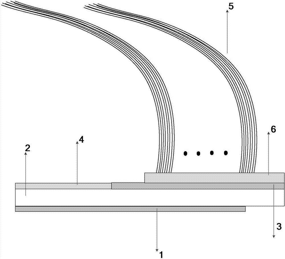
[0027] An optically controlled reconfigurable device for a phased array array antenna, such as figure 1 As shown, it includes a microstrip feeder layer 1, a microwave dielectric substrate 2, a hybrid covering layer, a laser array, a laser controller and an optical fiber bundle 5. The hybrid covering layer is formed by splicing silicon wafer layer 3 and metal layer 4 . The microwave dielectric substrate 2 is arranged on the upper surface of the microstrip feeder layer 1 , and the mixed covering layer is arranged on the upper surface of the microwave dielectric substrate 2 . One end of the fiber bundle 5 is connected to the laser emitting end of the laser array, and the other end of the fiber bundle is fixed on the upper surface of the silicon wafer layer 3 through a plastic fixing device 6 . The laser controller controls the opening and cl...


PUM


Abstract

The invention discloses a light-controlled reconfigurable apparatus of a phase-controlled-array array antenna. The light-controlled reconfigurable apparatus comprises a microstrip feeder line layer, a microwave dielectric substrate, a mixed coverage layer, a laser array, a laser controller and an optical fiber bundle, wherein the mixed coverage layer is formed by a silicon wafer layer and a metal layer in a spliced manner; the microwave dielectric substrate is arranged on the upper surface of the microstrip feeder line layer; the mixed coverage layer is arranged on the upper surface of the microwave dielectric substrate; one end of the optical fiber bundle is connected with the laser transmitting end of the laser array while the other end of the optical fiber bundle is fixed on the upper surface of the silicon wafer layer; the laser controller controls starting and closing of each laser in the laser array; a laser signal emitted from the laser array passes through the optical fiber bundle to be guided to irradiate an appointed region on the surface of the silicon wafer layer; and a phase-controlled signal is input from a feeder line port of the microstrip feeder line layer, and the starting and closing of each laser is changed through the laser controller so as to form array antennas of different caliber directions. Compared with the existing phase-controlled array antenna technology, the phase-controlled-array array antenna disclosed in the invention can obtain a larger space scanning angle.

Description

technical field [0001] The invention belongs to the technical field of phased array antennas, and in particular relates to an optically controlled reconfigurable device of a phased array array antenna. Background technique [0002] Phased array antenna is the most important antenna form in communication and radar. When the traditional antenna rotates the antenna mechanically, the inertia is large and the speed is slow. The phased array antenna overcomes this shortcoming, and the scanning speed of the beam is high and the beam directivity is high. However, at present, the maximum scanning angle that can be achieved by phased arrays can only reach about 60° from the normal direction. For large scanning angles, the beam directivity and antenna efficiency of phased arrays will deteriorate. [0003] The reconfigurable element antenna pattern can achieve the effect of expanding the scanning width of the phased array antenna, but because the array cannot be reconfigured according ...

Claims


Application Information

Patent Timeline
IPC IPC(8): H01Q1/52H01Q1/48H01Q1/38H01Q21/06
CPCH01Q1/38H01Q1/48H01Q1/52H01Q21/06H01Q21/061
Inventor 周永刚刘少斌闻乐天石春越薛喜亮
Owner NANJING UNIV OF AERONAUTICS & ASTRONAUTICS
Why Eureka
Try Eureka