TTE terminal system internal time synchronizing system and method

A time synchronization system and terminal system technology, applied in time division multiplexing system, electrical components, multiplexing communication, etc., can solve the problems of internal data transmission uncertain delay, clock asynchronous, etc., to solve the problem of internal clock Desynchronized, precision-enhancing effects

Active Publication Date: 2017-09-08
SHANGHAI INST OF TECH
View PDF5 Cites 16 Cited by
  • Summary
  • Abstract
  • Description
  • Claims
  • Application Information

AI Technical Summary

Problems solved by technology

[0003] The purpose of the present invention is to provide a TTE terminal system internal time synchronization system and method, to effectively solve the internal clock asynchronous TTE terminal system, uncertain delays in internal data transmission

Method used


Image

  • TTE terminal system internal time synchronizing system and method
  • TTE terminal system internal time synchronizing system and method
  • TTE terminal system internal time synchronizing system and method

Examples


Embodiment 1

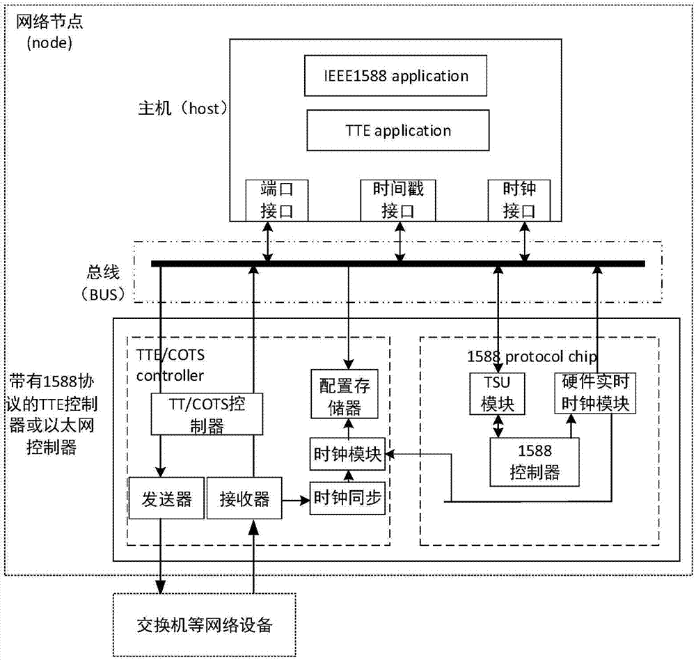
[0045] see figure 1 , figure 1It is a system block diagram of the internal time synchronization system of the TTE terminal system in the present invention. The system mainly includes a host and a communication controller, and the communication controller communicates with the host and at least one switch respectively, wherein the host is configured with a port interface, a time stamp interface and Clock interface, the communication controller communicates with the host through the bus (such as PCI bus) and port interface, time stamp interface, and clock interface; the communication controller has a transmitter and a receiver, and the transmitter and receiver are used to make the communication control The router communicates with at least one network device such as a switch.

[0046] The communication controller includes a TTE / COTS control module and a synchronization module. The synchronization module communicates with the host and the TTE / COTS control module respectively. Th...

Embodiment 2

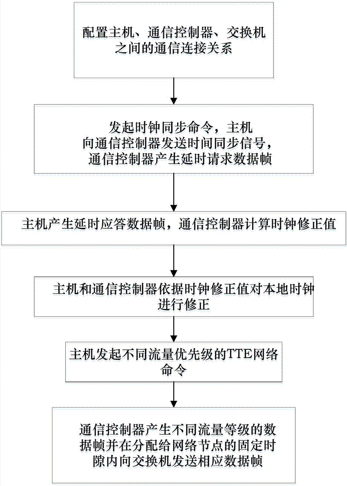
[0060] The present invention provides a method for internal time synchronization of a TTE terminal system, see figure 2 , the specific steps of the inter-synchronization method are:

[0061] S1. Configure the communication connection relationship between the host, the communication controller, and the switch, so that the communication controller communicates with the host and the switch;

[0062] S2. The host initiates the internal clock synchronization command of the terminal system and sends a time synchronization signal to the communication controller. After receiving the time synchronization signal, the communication controller generates a delay request data frame, and inserts a time stamp into the generated delay request data frame , and send the delayed request data frame with timestamp to the host;

[0063] S3. After the host receives the delay request data frame, it generates a delay response data frame, and returns the delay response data frame to the communication ...


PUM


Abstract

The invention relates to the technical field of communication network time synchronization, in particular to a TTE terminal system internal time synchronizing system and method. The system comprises a mainframe and a communication controller, wherein the communication controller is communicated with the mainframe and at least one switch, corrects the mainframe and its local clock according to a calculated clock correction value and produces data frames, and the data frames are sent to the switches in fixed time gaps allocated to network nodes. The mainframe sends a terminal system internal time synchronizing command and different flower levels of commands in a TTE network. According to the TTE terminal system internal time synchronizing method, the clock correction value is calculated according to data transfer between the mainframe and the communication controller, and the data frames are sent to the switches in the fixed time gaps. By adopting the system and method, the clock precision and clock output stability and certainty are improved, and deterministic transmission delay between the mainframe and the communication controller is ensured.

Description

technical field [0001] The invention relates to the technical field of communication network time synchronization, in particular to a system and method for internal time synchronization of a TTE terminal system. Background technique [0002] TTE system is widely used in avionics, unmanned vehicles and other fields because of its high reliability and high certainty. The TTE terminal system and switch are the main components of the TTE system. The TTE terminal system is a system composed of a host and a TT controller or an Ethernet controller connected through a CNI bus. However, in the existing TTE terminal system, the host and the control The uncertainty of communication delay between controllers directly affects the time for the host to send commands, and causes the time for the controller to receive and execute commands to be uncertain, which may lead to untimely messages. When the SM (synchronous controller) and CM (centralized controller) in the TTE network are used as ...

Claims


Application Information

Patent Timeline
Patent Type & Authority Applications(China)
IPC IPC(8): H04J3/06
CPCH04J3/0685
Inventor 赵琪赵怀林
Owner SHANGHAI INST OF TECH
Why Eureka
Try Eureka