Jaw type clamp

A jaw type and fixture technology, applied in the field of machining, can solve the problems of offset clamping position, poor reliability, complex structure, etc., and achieve the effects of accurate clamping position, improved service life and good operability

Inactive Publication Date: 2017-09-12
张帼威
View PDF0 Cites 5 Cited by
  • Summary
  • Abstract
  • Description
  • Claims
  • Application Information

AI Technical Summary

Problems solved by technology

Due to the complex structure of the current common clamps, the two jaws are mo

Method used


Image

  • Jaw type clamp
  • Jaw type clamp
  • Jaw type clamp

Examples


Embodiment Construction

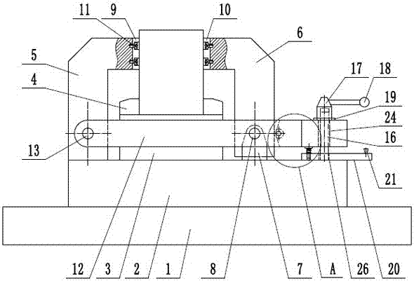
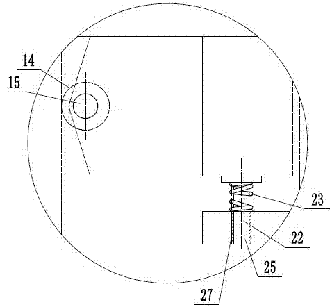
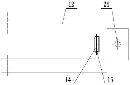
[0017] The present invention will be further described in detail below in conjunction with the accompanying drawings and examples. The following examples are explanations of the present invention and the present invention is not limited to the following examples.

[0018] Such as figure 1 , figure 2 and image 3 Shown, a kind of jaw type fixture, it comprises frame 1, supporting base 2, workpiece supporting platform 3, positioning plate 4, fixed jaw 5, movable jaw 6, jaw support 7, supporting pin shaft 8, Fixed clip 9, movable clip 10, fastening screw 11, Y-shaped lever 12, Y-shaped lever pin 13, driving roller 14, roller pole 15, fixed screw 16, pressure sleeve 17, grip handle 18 , pressure pad 19, support swing bar 20, rotating handle 21, push rod 22, support spring 23, described support base 2 is fixed on the frame 1, and described workpiece support platform 3 is fixed on the support base 2, and described workpiece The supporting platform 3 is provided with a positionin...


PUM


Abstract

The invention provides a jaw type clamp, which belongs to the technical field of mechanical processing. It includes a fixed jaw, a movable jaw, and a Y-shaped lever. The fixed jaw is fixed on the supporting base, the lower end of the movable jaw is hinged on the jaw support through the supporting pin, and the left end of the Y-shaped lever is passed through the Y-shaped lever pin. The shaft is hinged on the fixed jaw, and the driving roller can be rolled on the fork of the Y-shaped lever through the roller support rod. The fixed screw passes through the pin hole at the right end of the Y-shaped lever, and the upper end of the fixed screw is threaded with a pressure sleeve. There is a grip handle on the pressure sleeve, and a pressure pad is arranged between the pressure sleeve and the Y-shaped lever. The middle end of the supporting swing rod is hinged on the optical axis section at the lower end of the fixed screw rod. The other end of the swing rod is provided with a push rod groove, and the push rod can slide up and down to be arranged on the push rod groove. The invention adopts the structure of one fixed jaw and one movable jaw, so as to realize fast clamping of the workpiece, and the clamping position is accurate.

Description

technical field [0001] The invention relates to the technical field of mechanical processing, in particular to a jaw type clamp. Background technique [0002] Machining refers to the process of changing the shape or performance of a workpiece through a mechanical device. According to the difference in processing methods, it can be divided into cutting processing and pressure processing. The machinery required for processing consists of digital display milling machine, digital display forming grinder, digital display lathe, EDM machine, universal grinding machine, machining center, drilling machine, laser welding, fast wire walking, medium wire walking, slow wire walking, outer cylindrical grinder, inner circle Grinding machines, precision lathes, etc. Cutting processing refers to the processing method of using cutting tools (including cutting tools, grinding tools and abrasives) to cut off the excess material layer on the blank or workpiece into chips, so that the workpiece...

Claims


Application Information

Patent Timeline
IPC IPC(8): B23Q3/06
CPCB23Q3/066
Inventor 张帼威
Owner 张帼威
Why Eureka
Try Eureka